
Contactless method of supplying power

a contactless and wireless technology, applied in the direction of exchanging data chargers, safety/protection circuits, transportation and packaging, etc., can solve the problems of high manufacturing cost, inability to efficiently supply power from the power supply stand to the portable device, and complex circuit structure for foreign object detection. , to achieve the effect of stable, reliable detection and high output voltage of the receiving coil

Active Publication Date: 2013-10-31
SANYO ELECTRIC CO LTD
View PDF6 Cites 44 Cited by
  • Summary
  • Abstract
  • Description
  • Claims
  • Application Information

AI Technical Summary

Benefits of technology

The contactless method of supplying power described in this patent has the ability to detect foreign objects quickly and reliably using a simple circuit structure and low manufacturing cost. The method uses weighting values that increase depending on the size and change in requested power to determine if a foreign object is present. This allows for quick detection of foreign objects on the power supply stand. Additionally, the method includes a step-down process to supply power to the load, which reduces the need for wide wire runs and high energy density, and minimizes wasted power consumption during power transmission. Overall, this method improves the efficiency of contactless power distribution.

Problems solved by technology

This method of supplying power has the drawback that if a metal foreign object such as a paper clip is on the power supply stand when it is supplying power, current will be induced in the foreign object and heat will be generated due to Joule-heating.
Further, since wasted power is consumed by current induced in the foreign object, this method also has the drawback that power cannot be efficiently supplied from the power supply stand to the portable device.
Since the charging pad described above requires temperature sensors to detect foreign objects and decision circuitry to judge the presence of foreign objects from temperature detected by the temperature sensors, it has the drawbacks of complex circuit structure for foreign object detection and high manufacturing cost.
It also has drawbacks such as the inability to stably and reliably detect a foreign object positioned at a distance from the nearest temperature sensor, or delayed detection resulting in detrimental conditions such as excessive heat generated by the foreign object.
Further, since this charging pad judges the presence of a foreign object by detecting its heat generation with temperature sensors, the foreign object can be heated to an excessive temperature at the time of detection, and this has the drawback that the foreign object cannot be detected safely.
For example, this situation can result from position shift in the portable device due to a disturbance such as vibration during power transmission from the power supply stand to the portable device.
If power transmission efficiency drops, power received by the portable device will drop, and communication between the portable device and power supply stand can also become difficult making normal power supply impossible.

Method used


Image

  • Contactless method of supplying power
  • Contactless method of supplying power
  • Contactless method of supplying power

Examples


Embodiment Construction

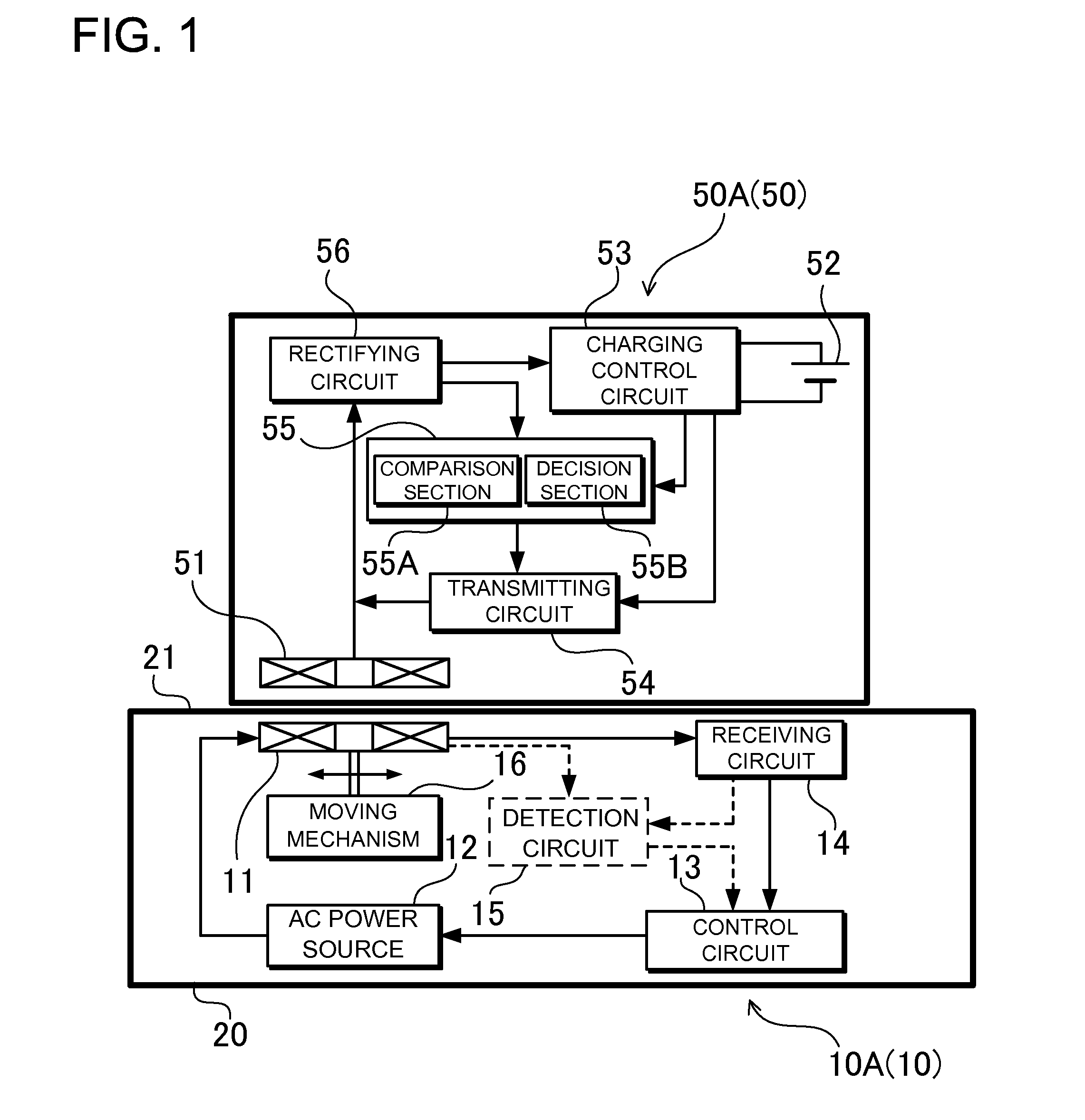
[0039]The following describes embodiments of the present invention based on the figures.

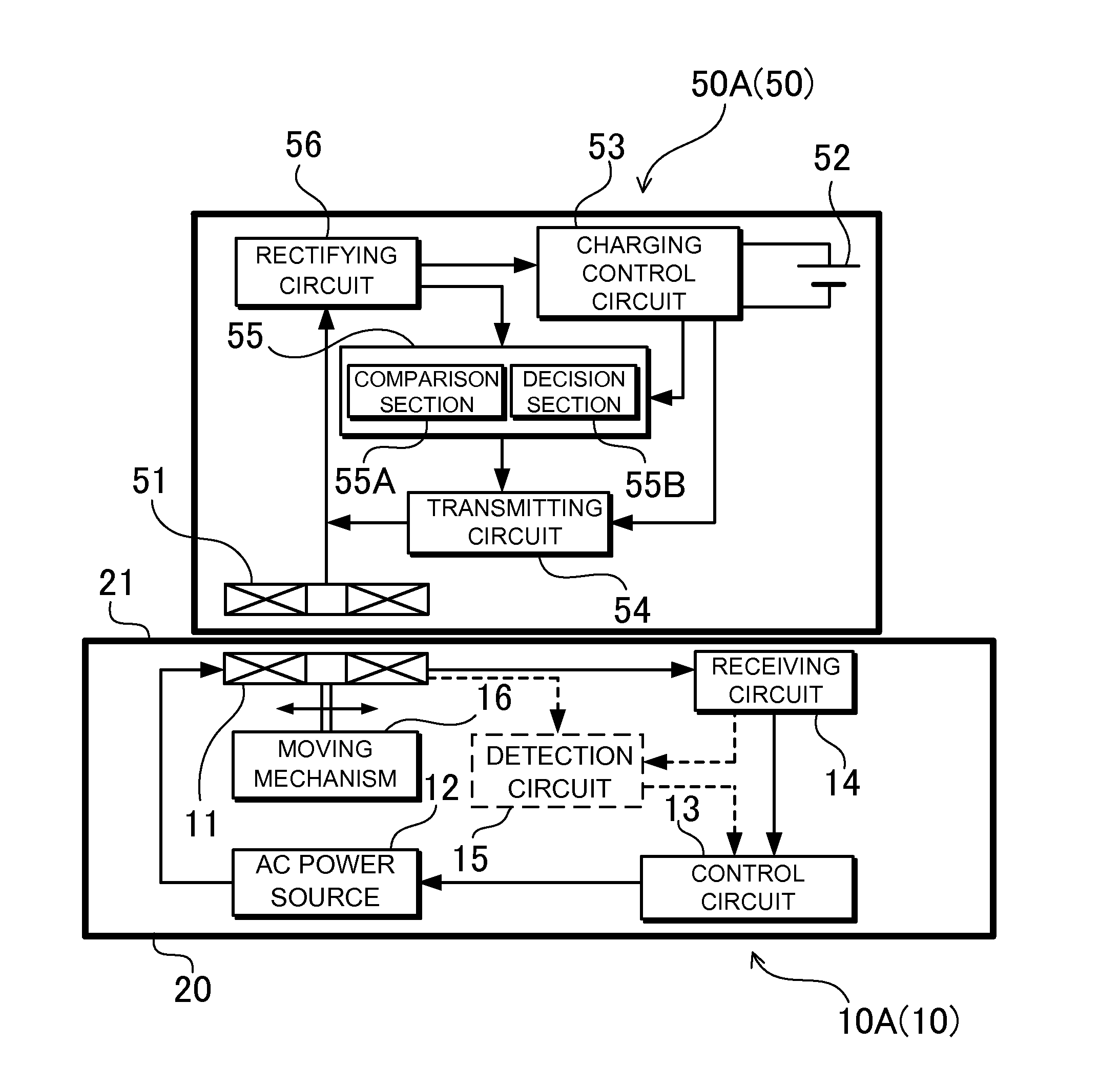
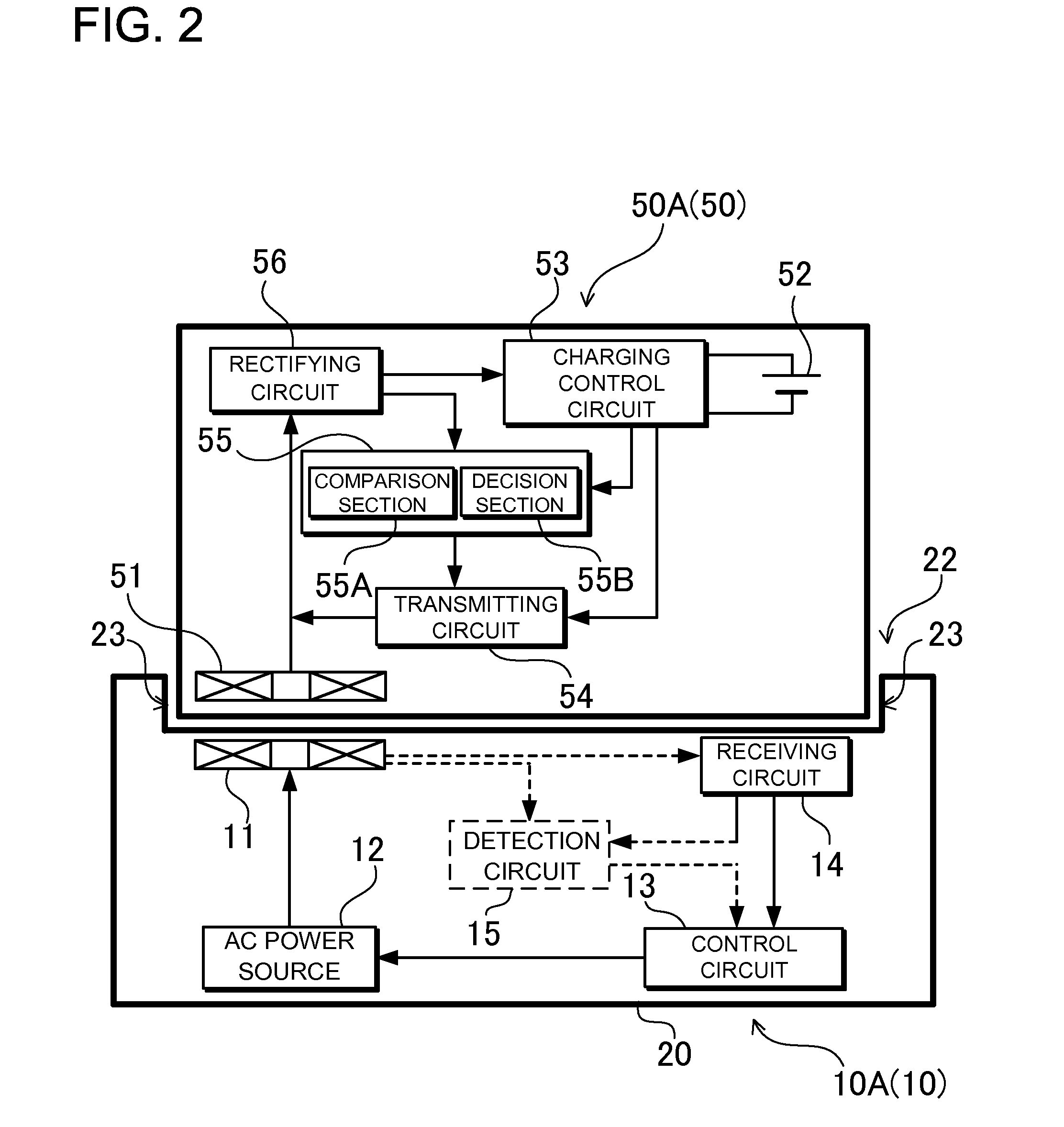
[0040]FIG. 1 is a block diagram showing a power supply stand that transmits power and portable device for the contactless method of supplying power of the present invention. This figure shows a portable device 50 placed on a power supply stand 10 to supply power from the power supply stand 10 to the portable device 50. In the embodiment described below, the power supply stand 10 is a charging pad 10A, the portable device 50 is a battery powered device 50A, and power is supplied from the charging pad 10A to the battery powered device 50A to charge a battery 52 housed in the battery powered device 50A.

[0041]However, the present invention does not limit the power supply stand to a charging pad and the portable device to a battery powered device.

[0042]Power can also be supplied from the power supply stand to a portable device that is an illumination device or a charging adapter. A portable device tha...


PUM


Abstract

The contactless method of supplying power magnetically couples a portable device receiving coil with a power supply stand transmitting coil and transmits power by magnetic induction. The portable device sends power adjustment signals to the power supply stand, and the stand adjusts transmitting coil output based on the power adjustment signals. The portable device compares the power received from the stand to the required power, sends an increase-power-request signal if the received power is below the required power, and sends a decrease-power-request signal if the received power is above the required power. Power adjustment signals include increase-power-request weighting values that increase with the size of the request to increase power and / or rate-of-change weighting values that increase with the amount of change in the requested power. Weighting values output with a given period are added and a foreign object is judged to be present when the sum attains a set value.

Description

BACKGROUND OF THE INVENTION[0001]1. Field of the Invention[0002]The present invention relates to a contactless (wireless) method of supplying power that disposes a transmitting coil and a receiving coil in close proximity to magnetically couple the coils to supply power from the transmitting coil to the receiving coil by magnetic induction, and in particular to a contactless method of supplying power that detects foreign objects on the power supply stand (pad, platform, stage, cradle).[0003]2. Description of the Related Art[0004]A contactless method of supplying power that places a portable device housing a receiving coil on a power supply stand housing a transmitting coil and transmits power from the transmitting coil to the receiving coil has been developed. (Refer to Japanese Laid-Open Patent Publication 2008-17562.)[0005]In the contactless method of supplying power of the related disclosure, a charging pad serves as the power supply stand, a battery powered device serves as the ...

Claims


Application Information

Patent Timeline
IPC IPC(8): H02J7/00H02J7/02
CPCH02J7/0029H02J7/025H02J50/10H02J50/90H02J7/00034H02J50/80H02J50/60H02J7/00
Inventor YAMAMOTO, HIROYOSHIWATANABE, RYOJITAMAI, MIKITAKA
Owner SANYO ELECTRIC CO LTD
Learn More