Optical amplifier repeater system

a repeater and optical amplifier technology, applied in the direction of electromagnetic repeaters, fault recovery arrangements, transmission monitoring, etc., can solve the problems of inability to generate a break and thereby not to be detected, and inability to detect abnormalities with a sufficient intensity

Inactive Publication Date: 2001-07-10
SUMITOMO ELECTRIC IND LTD
View PDF11 Cites 95 Cited by
  • Summary
  • Abstract
  • Description
  • Claims
  • Application Information

AI Technical Summary

Problems solved by technology

In the former, while the operations of the repeater stations located downstream from the break point of the optical transmission line are stopped, abnormalities of such a degree that no break is generated thereby cannot be detected.
When the distance from an optical amplifier to the break point is long, reflected return light with a sufficient intensity may not go back to the optical amplifier, whereby it may not be able to detect an abnormality even though there is a break in the optical transmission line.
If an abnormality occurs in the transmission line, then both of the signal light and monitor light exhibit a transmission failure.

Method used


Image

  • Optical amplifier repeater system
  • Optical amplifier repeater system
  • Optical amplifier repeater system

Examples


Embodiment Construction

In the following, preferred embodiments of the present invention will be explained in detail with reference to the accompanying drawings. For easier understanding of the explanation, constituents identical to each other among the drawings will be referred to with reference numerals identical to each other whenever possible, without their overlapping descriptions repeated.

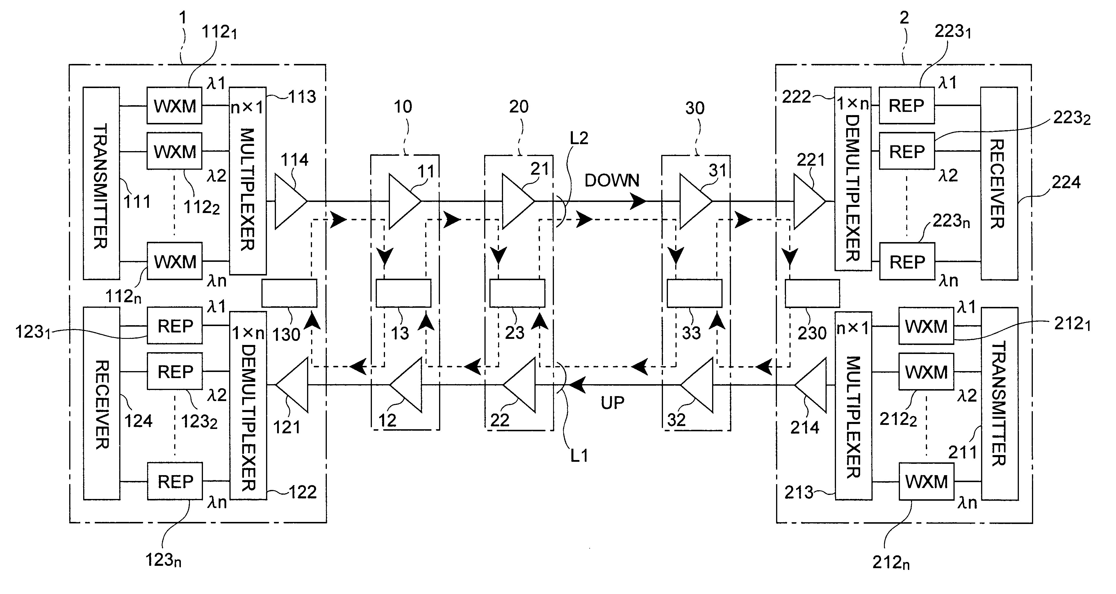
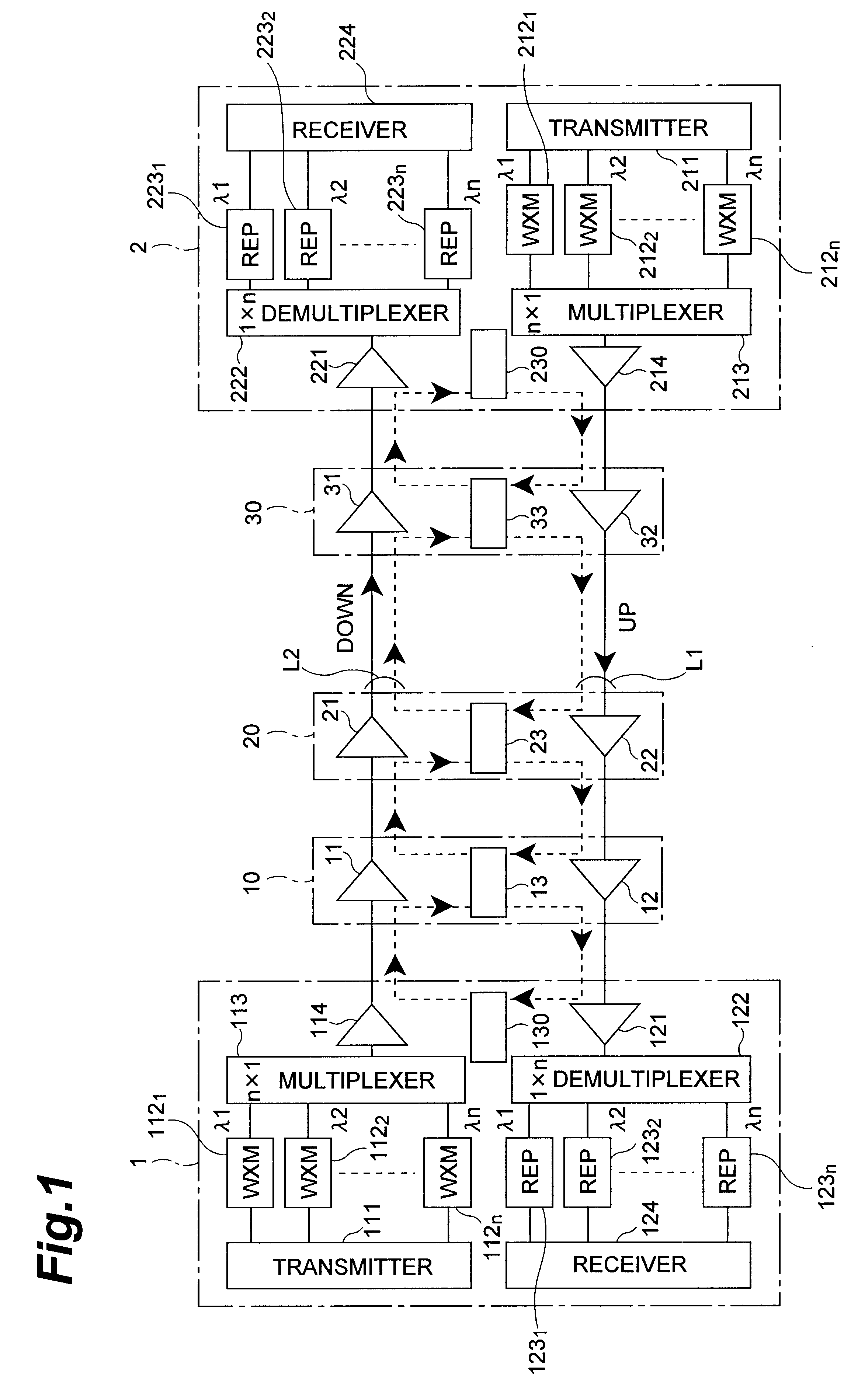
FIG. 1 is a configurational view of the optical amplifier repeater system in accordance with the present invention. This optical amplifier repeater system transmits signal light bidirectionally between a terminal station 1 and a terminal station 2, whereas repeater stations 10, 20, and 30 are disposed on an optical transmission line between the terminal station 1 and the terminal station 2. The optical transmission line is constituted, for example, by an optical fiber, and comprises a transmission line L1 for the direction (hereinafter referred to as "downstream direction") from the terminal station 1 to the termina...


PUM


Abstract

A repeater station 10 detects whether or not an abnormality exists in each of signal light and monitor light having arrived from a terminal station 1 or a repeater station 20, and controls, according to the result of detection, operations of optical amplifiers 11 and 12 and the monitor light. In the case where both of the signal light and monitor light arriving from the terminal station 1 via the optical transmission line for the downstream direction are abnormal, the optical amplifier 11 for the downstream direction stops its amplifying operation by itself, whereas a monitor control apparatus 13 stops the amplifying operation of the other optical amplifier for the upstream direction and also stops transmitting the monitor light to the terminal station 1 in the upstream direction.

Description

DESCRIPTION1. Technical FieldThe present invention relates to an optical amplifier repeater system which carries out bidirectional optical amplification and repeating of signal light by use of a plurality of repeater stations connected to each other in a multistage fashion.2. Background ArtEmployed for carrying out long-distance transmission in optical communications systems is a technique in which a plurality of repeater stations are connected to each other in a multistage fashion, while each repeater station is provided with an optical amplifier for amplifying the signal light transmitted thereto. In the case where an abnormality such as a break occurs at any location on an optical transmission line in such an optical amplifier repeater system, it is necessary to take steps to stop the operation of the optical amplifiers and remove the abnormality. To this end, it is required that the position where the abnormality has occurred be specified correctly.Known as techniques for sensin...

Claims


Application Information

Patent Timeline
Patent Type & Authority Patents(United States)
IPC IPC(8): H04B10/17H04B10/08H04B10/00H04B10/02H04B10/03H04B10/077H04B10/291H04B10/297
CPCH04B10/03H04B10/0775H04B10/0777H04B10/2972H04B10/2918H04B2210/08H04B2210/078H04B10/298H04B10/29
Inventor SHIGEMATSU, MASAYUKINISHIMURA, MASAYUKI
Owner SUMITOMO ELECTRIC IND LTD
Why Eureka
Try Eureka