
Dynamic balancing personal vehicle

Inactive Publication Date: 2009-05-07
SEGWAY INC
View PDF17 Cites 76 Cited by
  • Summary
  • Abstract
  • Description
  • Claims
  • Application Information

AI Technical Summary

Benefits of technology

[0006]The present invention provides among other things improvements in personal dynamic balancing vehicles. In one aspect, the present invention provides a vehicle interface unit for attaching a variety of rider interfaces to a dynamic balancing personal vehicle (DBPV). The rider interfaces envisioned include those that would allow standing, seated and elevated rider positions while operating the DBPV. The vehicle interface unit is secured to the DBPV so that forces from the rider are reliably transferred to the DBPV. The vehicle interface unit allows for rapid adjustment of the height of the rider interface while mounted on the DBPV. The depth of the rider interface “receiver” built into the vehicle interface determines the amount of height adjustment available. In a preferred embodiment six or more inches of vertical adjustment is provided. The absolute height of the rider seat is determined by the design of the rider interface.
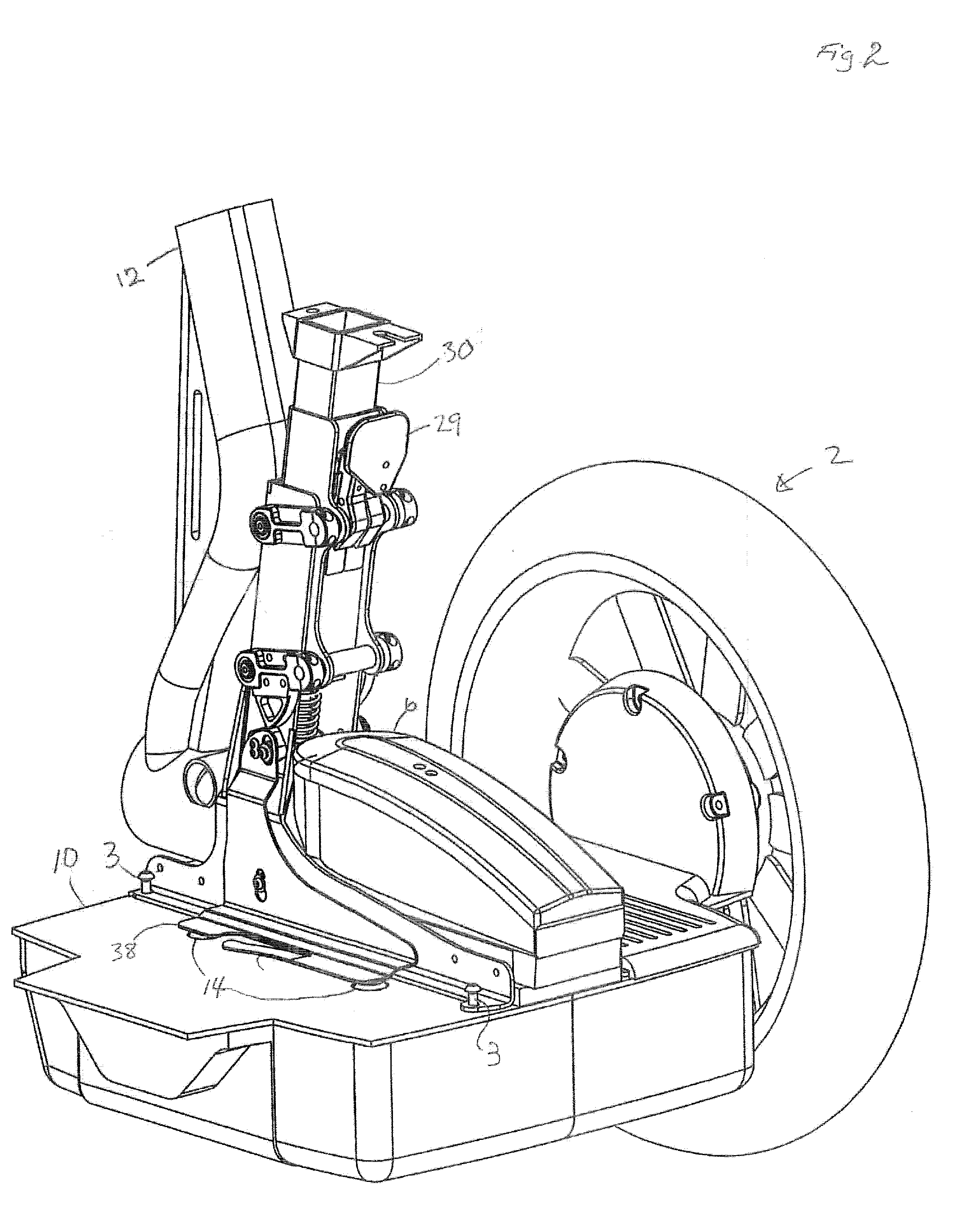
[0007]The rider interface receiver of the vehicle interface unit floats relative to the frame of the vehicle interface unit that is coupled to the DBPV. In one embodiment, the rider interface receiver is connected within the vehicle interface unit by a four-bar linkage that allows the rider interface receiver to move vertically through the two-step vertical movement relative to the DBPV. The first part of the vertical movement, e.g. ¼″ to ½″ travel, which is controlled by a spring, a cam and a cam follower, engages the rider present sensor switches in the DBPV to tell the vehicle that a rider is on board. The second part of the vertical movement, which may be 1″ to 2″, is controlled by a built-in shock reducer, preferably a combination of mechanical and gas springs, to reduce shock loads on the rider, the vehicle interface, and the entire DBPV system. The combination of functions, (rider force transfer into the DBPV, activation of rider present sensor switches, height adjustment and shock reduction), in the vehicle interface unit simplifies the rider interfaces, and allows for rapid switching of rider interfaces to meet the needs of the rider.
[0008]In another aspect, the present invention provides a seating system for mounting to a DBPV that permits rapid transition from standing only operation, standing with support operation, standing to seated to standing operation, and seated only operation. The “standing with support operation and standing to seated to standing operation” seat system in the preferred embodiment employs a seat similar to a unicycle design as the rider interface to permit use both in a standing and seated mode. The seat is mounted on a rail that permits the user to move the seat back and forth to trim their center of gravity on the DBPV. The rider uses height adjustment provided by the vehicle interface unit and rider interface to set the height of the seat to the rider's preference while either off the DBPV or while standing on the DBPV. The “seated only operation” seat system in another embodiment employs a platform or bench seat which limits use to a seated only mode. The seating platform is mounted on a frame that permits the user to move the seating platform back and forth to trim the rider's center of gravity on the DBPV. The rider uses height adjustment provided by the vehicle interface and rider interface to set the height of the platform to the rider's preference while off the DBPV. The addition of a powered, or mechanically advantaged lift system allows for height adjustment while the rider is on the platform.
[0012]It is another object of the invention to provide a seating system to be easily attached to a conventional commercially available dynamic balancing personal vehicle, such as a SEGWAY PERSONAL TRANSPORTER dynamic balancing personal vehicle, without modifying any of the software of the commercially available vehicle.
[0015]It is yet another object of the invention to provide improved mobility and comfort for the mobility impaired.

Problems solved by technology

While self-balancing personal vehicles have achieved a certain amount of commercial success, they have several limitations.
This can be tiring, particularly for the elderly and / or infirm, and may be difficult or impossible for the mobility impaired.

Method used


Image

  • Dynamic balancing personal vehicle
  • Dynamic balancing personal vehicle
  • Dynamic balancing personal vehicle

Examples


Embodiment Construction

[0028]In the following description, and for the purposes of explanation, numerous specific details are set forth in order to provide a thorough understanding of the various aspects of the invention. It will be understood, however, by those skilled in the relevant arts, that the present invention may be practiced without these specific details. In other instances, known structures and devices are shown or discussed more generally in order to avoid obscuring the invention. In many cases, a description of the operation is sufficient to enable one to implement the various forms of the invention, particularly when the operation is to be implemented in software. It should be noted that there are many different and alternative configurations, devices and technologies to which the disclosed invention may be applied. The full scope of the invention is not limited to the examples that are described below.

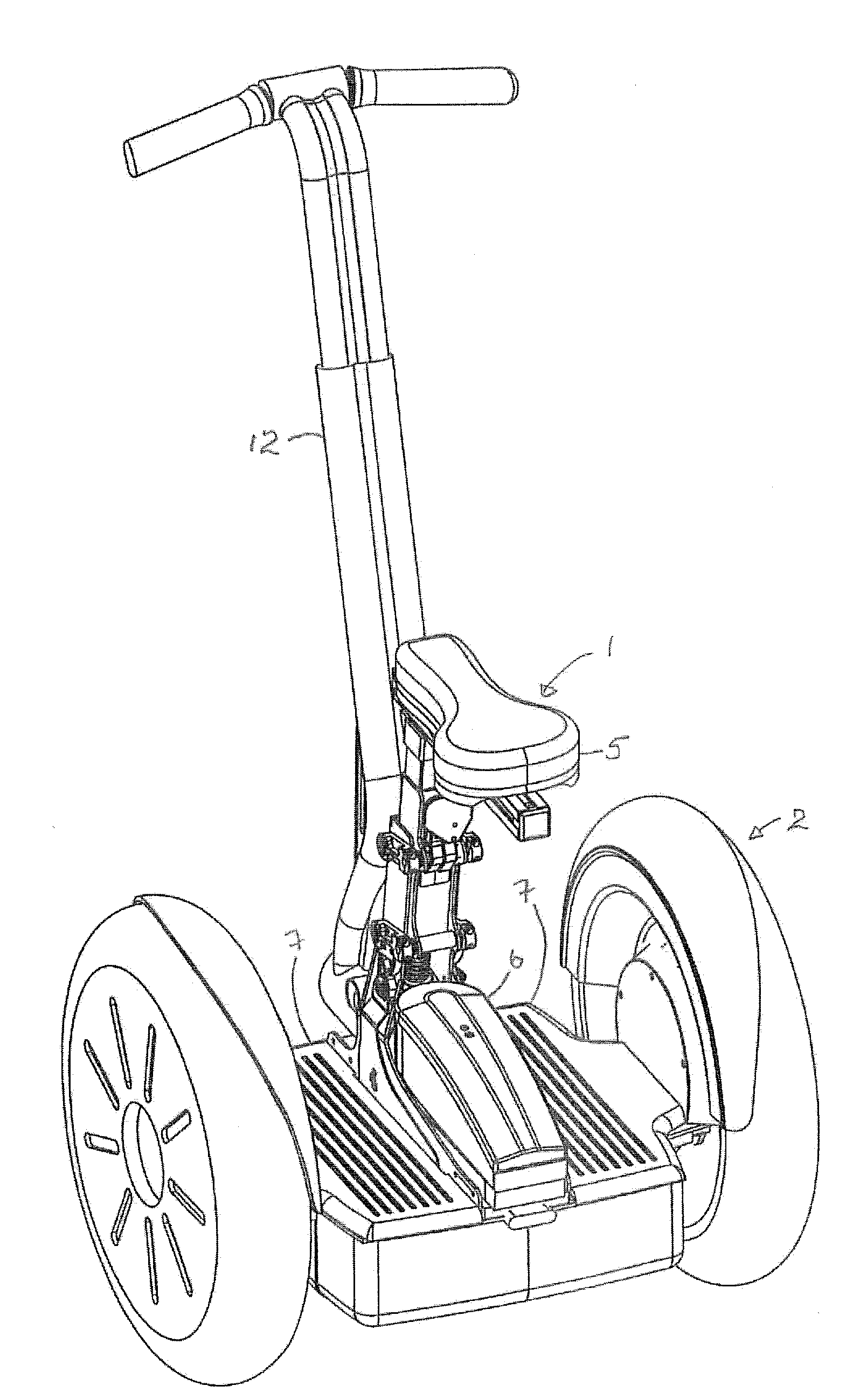
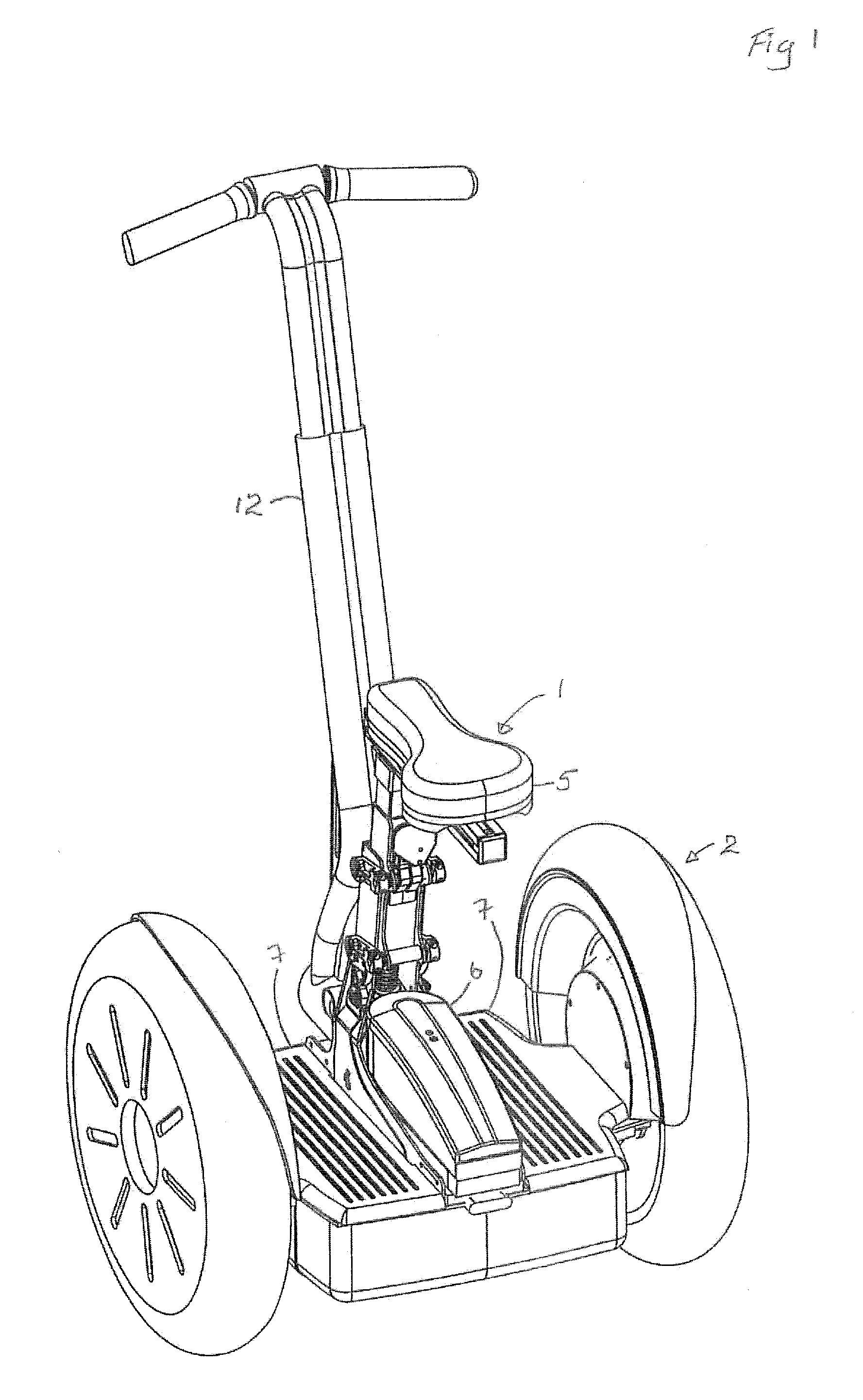
[0029]Referring to FIGS. 1-9, there is shown a seat system 1 mounted to an commercially a...


PUM


Abstract

A seating system to be easily attached to an existing dynamic balancing personal vehicle is provided. The seating system allows both seated and standing use of the dynamic balancing personal vehicle, and provides for activation of rider present sensors contained in the foot platform of the dynamic balancing personal vehicle by the weight of the rider on the seating system. The seating system also provides for secure transfer of rider forces into the attached dynamic balancing personal vehicle, as well as shock attenuation, rider height adjustment, and rider center of gravity trimming. Alternatively, a dynamic balancing transportation system incorporating a flexible seating system for a rider is provided.

Description

CROSS REFERENCE TO RELATED APPLICATION[0001]The present application claims the benefit of Provisional Application 60 / 985,576 filed Nov. 5, 2007.FIELD OF THE INVENTION[0002]The present application relates to improvements in dynamic balancing personal vehicles. The invention has particular utility as improvements to dynamic balancing personal vehicles such as are available commercially under the trade name “SEGWAY PERSONAL TRANSPORTER”, from Segway, Inc., Manchester, N.H., and will be described in connection with such utility, although other utilities are contemplated.BACKGROUND[0003]Self-powered, user guidable dynamic balancing personal vehicles are available commercially and are described in the patent art. See, for example, U.S. Pat. No. 5,871,091, the contents of which are incorporated by reference. Vehicles of this type operate in a mode in which motion of the vehicle, including acceleration is controlled partially or entirely by leaning or weight shift of the subject riding the ...

Claims


Application Information

Patent Timeline
IPC IPC(8): B60G17/00
CPCB60N2/002B60N2/163B60N2/1685B60N2/169B62K3/007B60N2/507B60N2/525B60N2/544B60N2/502B62K11/007
Inventor WALLIS, SCOTT E.HUGHES, BRIAN G. R.
Owner SEGWAY INC
Learn More