LED driving circuit and controlling method thereof

Inactive Publication Date: 2007-05-17
SHENZHEN TXM POWER
View PDF4 Cites 44 Cited by
  • Summary
  • Abstract
  • Description
  • Claims
  • Application Information

AI Technical Summary

Benefits of technology

[0016] 3. having a small volume, high efficiency and high power factor. This driving circuit is designed small enough to be directly installed in an ordinary lamp holder, such that LEDs may directly substitute for the currently used luminaire. As the off-time is modulated with the input voltage, the power factor may thereby be higher than 0.95, and the efficiency than 95%.
[0017] 4. having enhanced LED luminous intensity and prolonged LED lifetime. Since the constant current provided by the present invention is fully controllable, the maximum current flowing through LEDs may be ad

Problems solved by technology

In this case, the efficiency is so low that supplying electricity to an LED of 1W will consume power of 4-6W in the grid; and the power factor is extremely low, up to about 0.2, which not only causes heavy pollution to the grid, but also significantly reduces the lifetime of LEDs.
Due to its bulkiness, the brightness consistency of LEDs used in batches is poor.
In addition, EMI (ElectroMagnet

Method used


Image

  • LED driving circuit and controlling method thereof
  • LED driving circuit and controlling method thereof
  • LED driving circuit and controlling method thereof

Examples


example 1

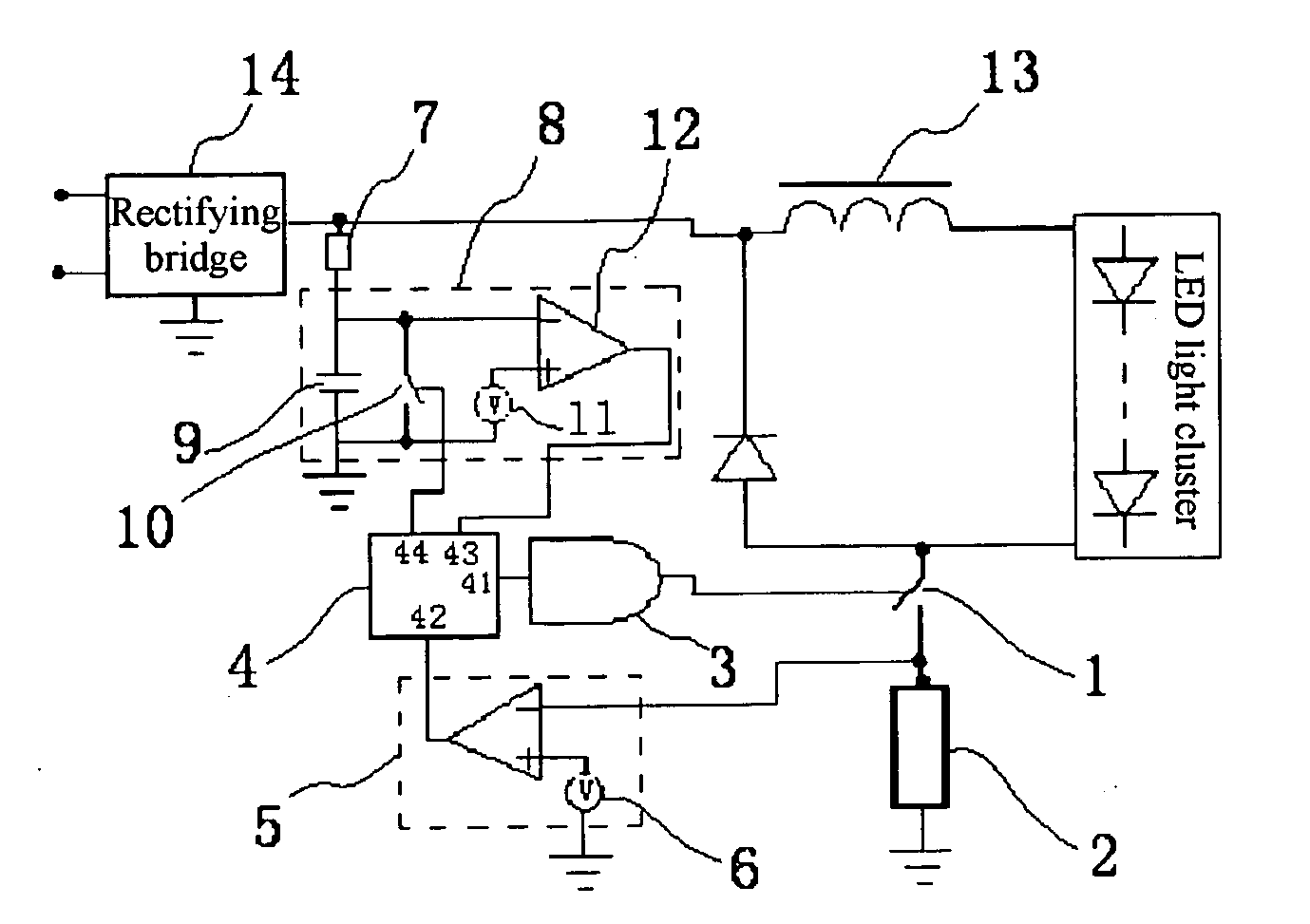
[0025] As shown in FIG. 3, in addition to a power switch 1 and a current sampling unit 2 for sampling LED operating current, there are further comprised: a voltage comparison unit 5 for comparing the voltage obtained by the current sampling unit 2 with the voltage of a first reference voltage source 6 (see FIG. 5); an input voltage sampling unit 7 for converting the sampled input voltage into a current signal; a timing unit 8 for controlling the off-time of the power switch 1 based on the magnitude of the input voltage collected by the input voltage sampling unit 7; a logical unit 4 for controlling the power switch 1 by means of a power switch driving unit 3, based on the comparison of the voltage comparison unit 5 and the output signal of the timing unit 8, and for controlling the timing switch 10 in the timing unit 8. As shown in FIG. 5, the current sampling unit 2 is a resistor or a current coupling device connected in series with the power switch 1, preferably a resistor in this...

example 2

[0029] As shown in FIG. 4, in addition to a power switch 1 and a current sampling unit 2 for sampling LED operating current, there are further comprised: a voltage comparison unit 5 for comparing the voltage obtained by the current sampling unit 2 with the voltage of a first reference voltage source 6 (see FIG. 6); a timing unit 8 for setting a fixed off-time for the power switch 1; a logical unit 4 for controlling the power switch 1 by means of a power switch driving unit 3, based on the comparison of the voltage comparison unit 5 and the output signal of the timing unit 8, and for controlling the timing switch 10 in the timing unit 8.

[0030] As shown in FIG. 6, the current sampling unit 2 is a resistor or a current coupling device connected in series with the power switch 1, preferably a resistor in this embodiment, for converting the sampled current signal into a voltage signal. When the voltage obtained by the current sampling unit 2 reaches the voltage of the first reference vo...


PUM


Abstract

The invention discloses an LED driving circuit and a controlling method thereof, comprising a power switch and a current sampling unit, as well as a voltage comparison unit for comparing the voltage obtained by the current sampling unit with a first reference voltage; an input voltage sampling unit for converting the sampled input voltage into a current signal; a timing unit for controlling the off-time of the power switch or presetting a fixed off-time; a logical unit for controlling the power switch by means of a power switch driving unit and for controlling the timing switch in the timing unit. The method for controlling the LED driving circuit comprises the step of modulating the off-time of the power switch with the input voltage or the step of presetting a fixed off-time. The invention can be used in LED light cluster driving with the power factor greater than 0.95.

Description

RELATED APPLICATION [0001] The present application claims the priority of the Chinese Patent Application No. 200510124707.4, filed Nov. 11, 2005, titled “LED Driving Circuit and Controlling Method Thereof”, which is incorporated herein by reference in its entirety. FIELD OF THE INVENTION [0002] The invention relates to a power supply driving circuit and a controlling method thereof, and in particular, to a driving circuit and controlling method for LED. BACKGROUND OF THE INVENTION [0003] With large power LEDs being widely used in lighting and illumination, power-type LED driving circuits are increasingly important. Additionally, the luminous intensity of an LED, which is a current-type semiconductor light emitting device, is determined by the current flowing through the LED. Therefore, a power supply, which provides a constant current for driving LEDs, is in earnest demand. [0004] Currently, two kinds of methods are commonly used for driving LEDs by means of electric mains (220 V or...

Claims


Application Information

Patent Timeline
IPC IPC(8): H05B41/24
CPCH05B33/0815H05B45/3725
Inventor WANG, JIZHANG, YIMIN
Owner SHENZHEN TXM POWER
Why Eureka
Try Eureka