Energy transferring system and method thereof

a technology of energy transfer and energy transfer, which is applied in the field of energy transfer devices and, can solve the problems of q-factor resonators, high cost, and large volume, and achieve the effect of reducing cost, reducing volume, and increasing efficiency

Inactive Publication Date: 2011-08-09
DARFON ELECTRONICS CORP
View PDF27 Cites 184 Cited by
  • Summary
  • Abstract
  • Description
  • Claims
  • Application Information

AI Technical Summary

Benefits of technology

[0008]The invention is directed to an energy transferring system and a method thereof. Compared with the conventional wireless power transferring system, the energy transferring system of the invention has the advantages of higher energy transferring efficiency, smaller volume, and lower cost.

Problems solved by technology

However, such Q-factor resonator, which occupies a large volume and costs a lot, cannot be used in ordinary electronic products.
Moreover, when the transferring distance is remote, the transferor can only achieve low efficiency in the transfer of energy.

Method used


Image

  • Energy transferring system and method thereof
  • Energy transferring system and method thereof
  • Energy transferring system and method thereof

Examples


Embodiment Construction

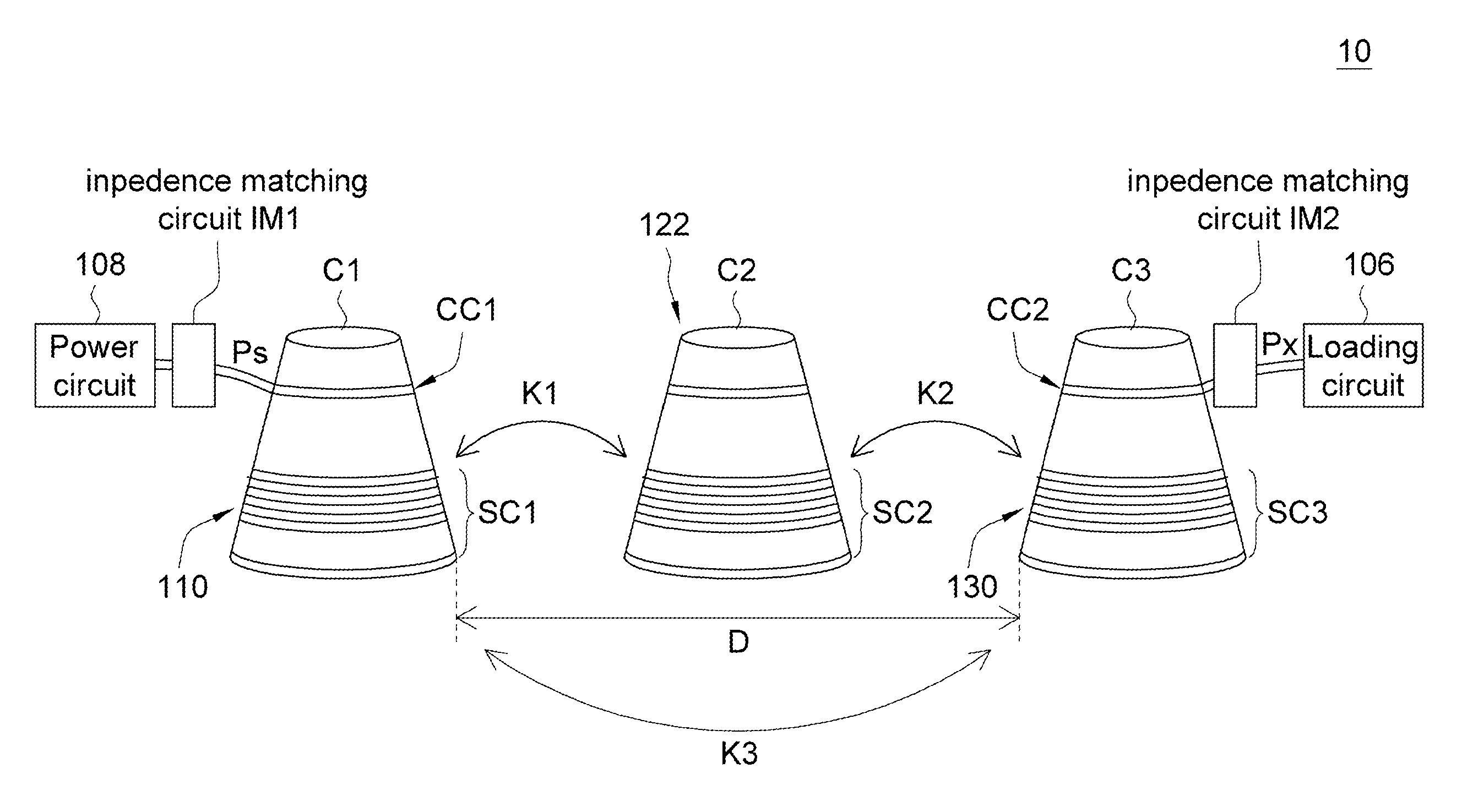
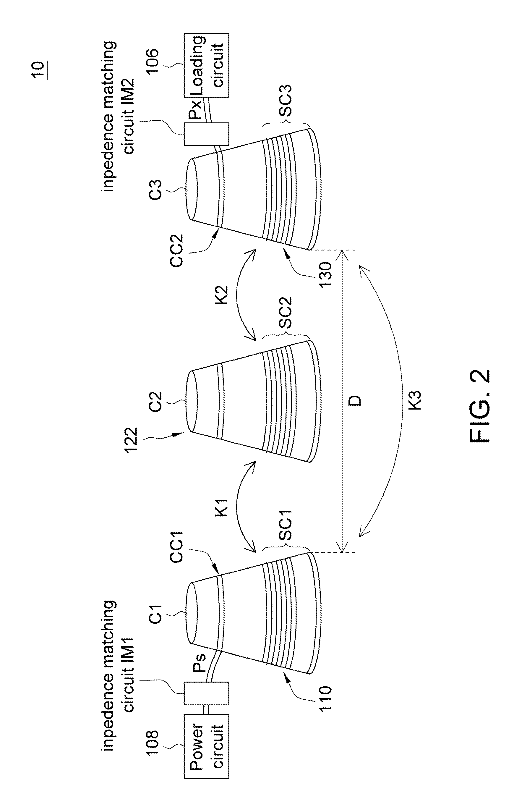
[0026]According to an energy transferring system of the invention, an intermediate resonant module is disposed between a source-side resonator and a device-side resonator for coupling energy from the source-side resonator and for coupling energy to the device-side resonator such that the overall transferring efficiency between the source-side resonator and the device-side resonator is enhanced.

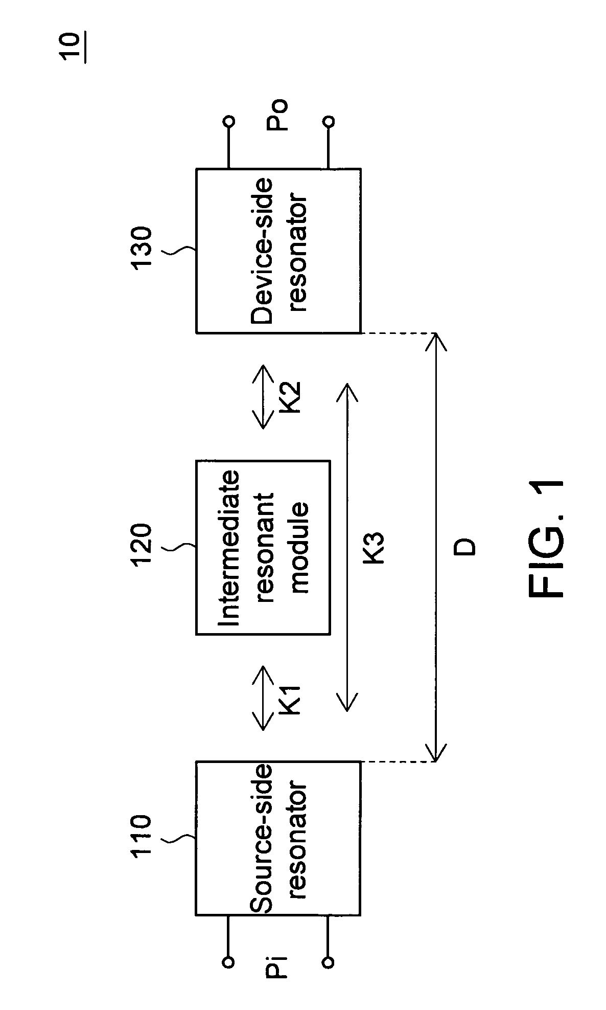
[0027]Referring to FIG. 1, a block diagram of an energy transferring system according to an embodiment of the invention is shown. The energy transferring system 10 includes a source-side resonator 110, an intermediate resonant module 120 and a device-side resonator 130. The source-side resonator 110 receiving an energy Pi has a resonant frequency f1.

[0028]The intermediate resonant module 120 includes at least one intermediate resonator having a resonant frequency f2 substantially the same with the resonant frequency f1. The energy Pi on the source-side resonator 110 is coupled to the intermedi...


PUM


Abstract

An energy transferring system including a source-side resonator, an intermediate resonant module, and a device-side resonator is provided. The three resonators substantially have the same resonant frequency for generating resonance. The energy on the source-side resonator is coupled to the intermediate resonant module, such that non-radiative energy transfer is performed between the source-side resonator and the intermediate resonant module. The energy coupled to the intermediate resonant module is further coupled to the device-side resonator, such that non-radiative energy transfer is performed between the intermediate resonant module and the device-side resonator to achieve energy transfer between the source-side resonator and the device-side resonator. The coupling coefficient between the intermediate resonant module and its two adjacent resonators is larger than the coupling coefficient between the source-side resonator and the device-side resonator. The invention has the advantages of high transmission efficiency, small volume, low cost.

Description

[0001]This application claims the benefit of Taiwan application Serial No. 096148037, filed Dec. 14, 2007, the subject matter of which is incorporated herein by reference.BACKGROUND OF THE INVENTION[0002]1. Field of the Invention[0003]The invention relates in general to an energy transferring device and a method thereof, and more particularly to an energy transferring device which achieves energy transfer through energy coupling between resonators and a method thereof.[0004]2. Description of the Related Art[0005]There are many techniques of wireless transmission already used in the field of communication. Currently, conventional techniques of wireless transmission are mostly used in the reception and transmission of signals, and are hence only applicable to the transmission of low power signals.[0006]As there are more and more electronic products adopt wireless transmission, the development of wireless transmission applicable to high power signals attracts more and more attention. U...

Claims


Application Information

Patent Timeline
Patent Type & Authority Patents(United States)
IPC IPC(8): H01P7/00H03H2/00H02J50/12H02J50/50
CPCG08C17/04
Inventor CHEN, CHIH-JUNGLIN, CHIH-LUNGJOU, ZUEI-CHOWN
Owner DARFON ELECTRONICS CORP
Why Eureka
Try Eureka