Energy transmitting terminal and energy wireless transmission method

A technology of energy transmission and wireless energy, applied in the direction of electrical components, circuit devices, electromagnetic wave systems, etc., can solve the problems of wireless energy transmission security decline, low wireless energy transmission efficiency, low transmission efficiency and transmission power

Active Publication Date: 2014-07-23
TSINGHUA UNIV
View PDF5 Cites 24 Cited by
  • Summary
  • Abstract
  • Description
  • Claims
  • Application Information

AI Technical Summary

Problems solved by technology

The coupling coefficient between the above two kinds of transmitting coils and receiving coils is low, resulting in low efficiency of wireless energy transmission
On the one hand, a cable needs to be connected to the device for power supply, which limits the freedom of the patient; on the other hand, the greater transmission power brought about by the low transmission efficiency exposes the patient to stronger electromagnetic radiation, which leads to the safety of wireless energy transmission decline

Method used


Image

  • Energy transmitting terminal and energy wireless transmission method
  • Energy transmitting terminal and energy wireless transmission method
  • Energy transmitting terminal and energy wireless transmission method

Examples


Embodiment 1

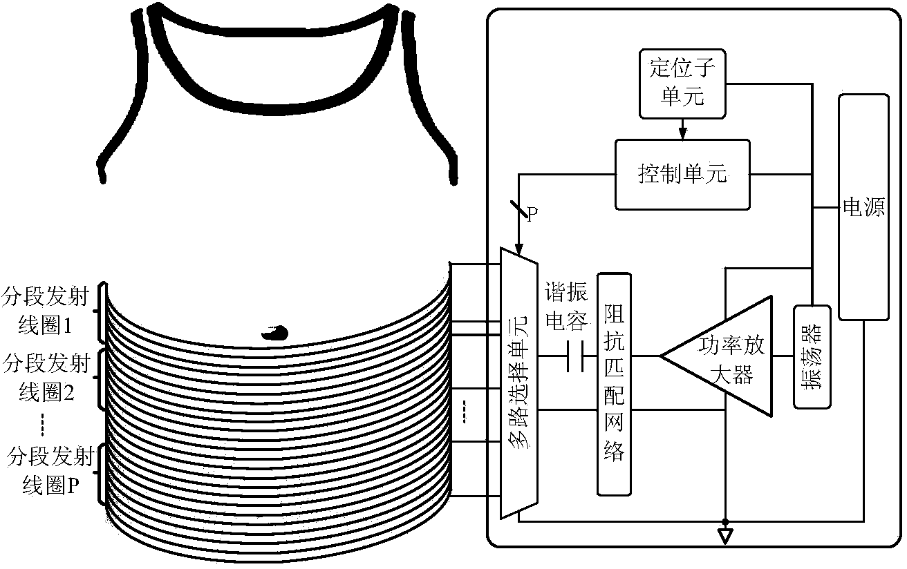
[0086] As shown in Fig. 1(a), the energy transmitting end of this embodiment includes: multiple groups of segmented energy transmitting coils, an energy supply unit, a multiplexing unit, a positioning subunit and a control unit. Among them, the multi-group segmented energy transmitting coils are used for wireless energy generation; the multiplex unit is used to control the orderly access of the multi-group segmented transmitting coils;

[0087] The positioning subunit is used to obtain the position coordinates of the energy receiving end (that is, the movable implantable medical device); currently known positioning technologies include radio positioning, acoustic wave positioning, magnetic field positioning, etc., and the positioning accuracy is within 1cm. Due to the positioning function The specific implementation is a known technology, so it will not be described in detail in the present invention. In addition, it is considered that the realization of the positioning sub...

Embodiment 2

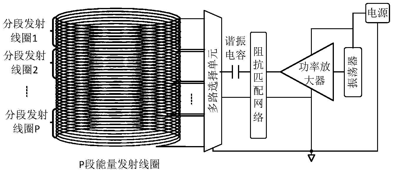
[0116] As shown in Figure 2(a), the difference between this embodiment and Embodiment 1 is: the energy transmitting end does not have a positioning subunit, but a wireless data receiving subunit is added, and the energy receiving end needs to contain an energy acquisition unit and a wireless Data sending unit. The wireless data receiving subunit outside the body and the wireless data sending unit inside the body can be shared with the wireless transceiver system originally contained in the movable implantable system (such as the wireless capsule system), and only need to transfer the wireless energy intensity data and the energy receiving The data to be transmitted at the end can be integrated and transmitted together.

[0117] Assume that the energy receiving end is initially located in the area surrounded by the segmented energy transmitting coil 2, and the segmented transmitting coil 2 is the working coil. However, as the detection time goes by, the energy receiving end...

Embodiment 3

[0124] As shown in Figure 3(a), the difference between this embodiment and Embodiment 2 is that each segmented energy transmitting coil is equipped with a capacitor that resonates with it, so that two There are two segmented energy transmitting coils, and the currents in the two segmented transmitting coils need to maintain the same phase. The change of the access coil makes its impedance change, so its impedance matching network needs to be adjusted accordingly. As shown in Figure 3(b), there are two kinds of matching networks. When accessing a single segmented transmitting coil, the control unit connects the "matching network when a single segmented transmitting coil works" between the power amplifier and the multiplexing unit; when accessing two segmented transmitting coils, the control unit Connect the "Matching Network When Two Segmented Transmitting Coils Work" between the power amplifier and the multiplexing unit. And the control unit controls the connection between ...


PUM


Abstract

The invention discloses an energy transmitting terminal and an energy wireless transmission method, and relates to the technical field of energy wireless transmission. According to the energy transmitting terminal and the energy wireless transmission method, the optimal segmentation energy transmitting coil is selected according to location information of the energy transmitting terminal, the coefficient of coupling between the segmentation energy transmitting coil and a receiving coil can be increased, the energy transmission efficiency is improved, and electromagnetic radiation received by a patient is reduced; due to the fact that energy supply can be carried out through a portable lithium battery, the patient can be more free.

Description

technical field [0001] The present invention relates to the technical field of wireless energy transmission, in particular to an energy transmitter and a wireless energy transmission method. Background technique [0002] The emergence of capsule endoscope has brought medical endoscope technology into a new era. It not only solves the defect that traditional endoscope cannot inspect the small intestine, but also greatly reduces the pain of patients. However, currently existing movable implantable medical devices are only equipped with 1 or 2 cameras, and can only rely on the peristalsis of the intestinal tract to move passively, and then take images of the intestinal tract. With the continuous increase of clinical needs, movable implantable medical devices need to integrate more functions, such as wireless endoscopic capsules for active movement through propellers, capsules for injecting drugs through needles, mechanical devices to achieve Movable implantable medical devices...

Claims


Application Information

Patent Timeline
Patent Type & Authority Applications(China)
IPC IPC(8): H02J17/00H02J50/10
Inventor 谢翔黄亚东李国林谷荧柯李欢欢王志华
Owner TSINGHUA UNIV
Why Eureka
Try Eureka