System for improving a spatial effect of stereo sound or encoded sound

Inactive Publication Date: 2003-07-01
3S TECH
View PDF11 Cites 47 Cited by
  • Summary
  • Abstract
  • Description
  • Claims
  • Application Information

AI Technical Summary

Problems solved by technology

Further, there is a problem that the signal component is lacking in the middle frequency range, i.e. in a voice frequency range, and in the low frequency range, since most of the component of such processed signal are distributed in the high frequency range.
However, in such a signal processing system, since the original stereo signal is processed in various manners to obtain L+R and L-R signals and these signals are reconstructed at the matrix steps after getting the frequency compensation, a large amount of the original sound signal is lost while the three dimensional sense of sound may be obtained.
In addition to this, when the original stereo signals are reconstructed, some of the original sound is lost.
Therefore, if a consumer hears such

Method used


Image

  • System for improving a spatial effect of stereo sound or encoded sound
  • System for improving a spatial effect of stereo sound or encoded sound
  • System for improving a spatial effect of stereo sound or encoded sound

Examples


first embodiment

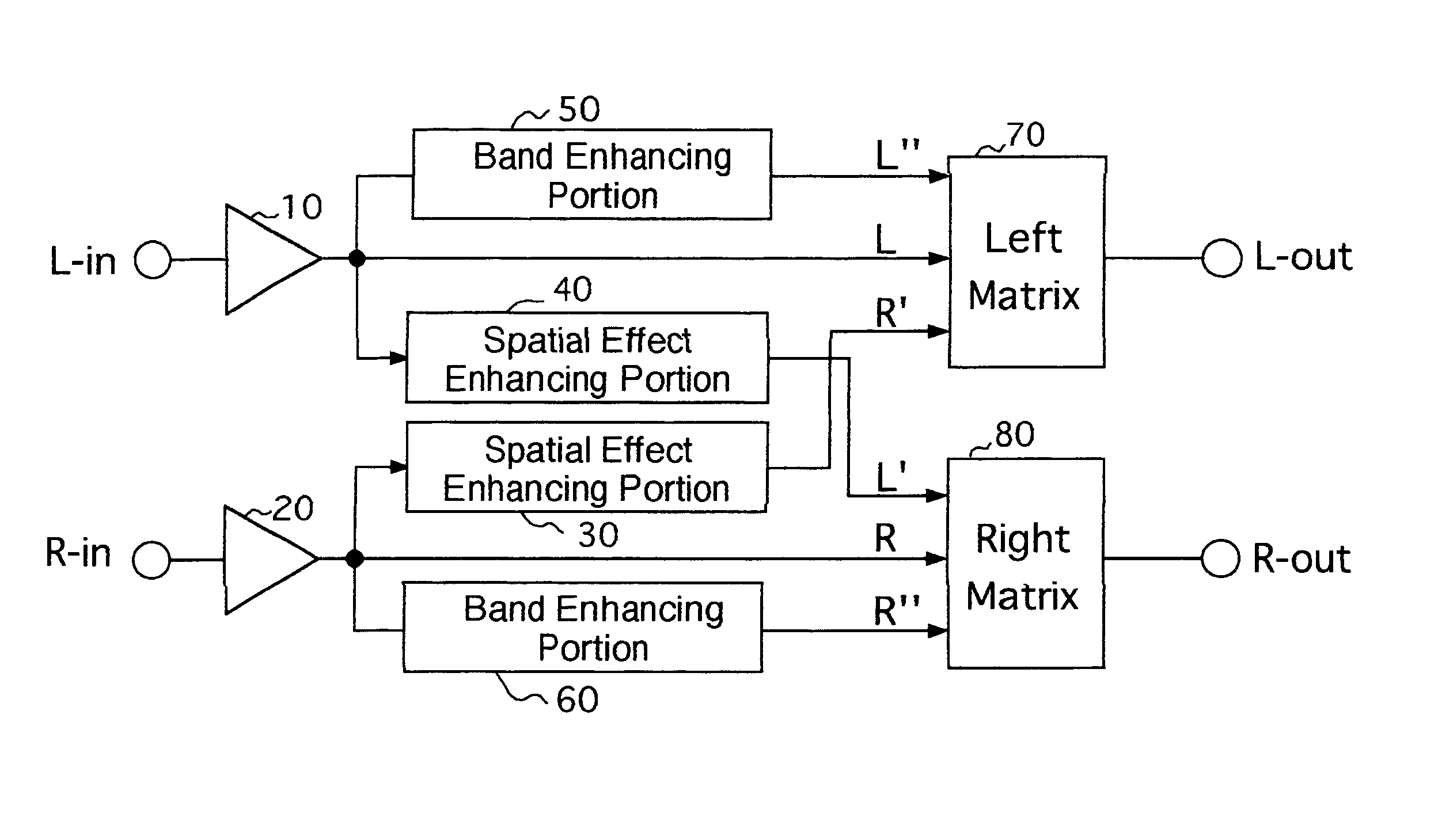
FIG. 1 is a block diagram showing a basic construction of the system for improving a spatial effect of stereo sound or encoded sound according to the invention. The system is applied to audio equipment as a signal processor where a three dimensional stereo sound image signal is produced from stereo signals.

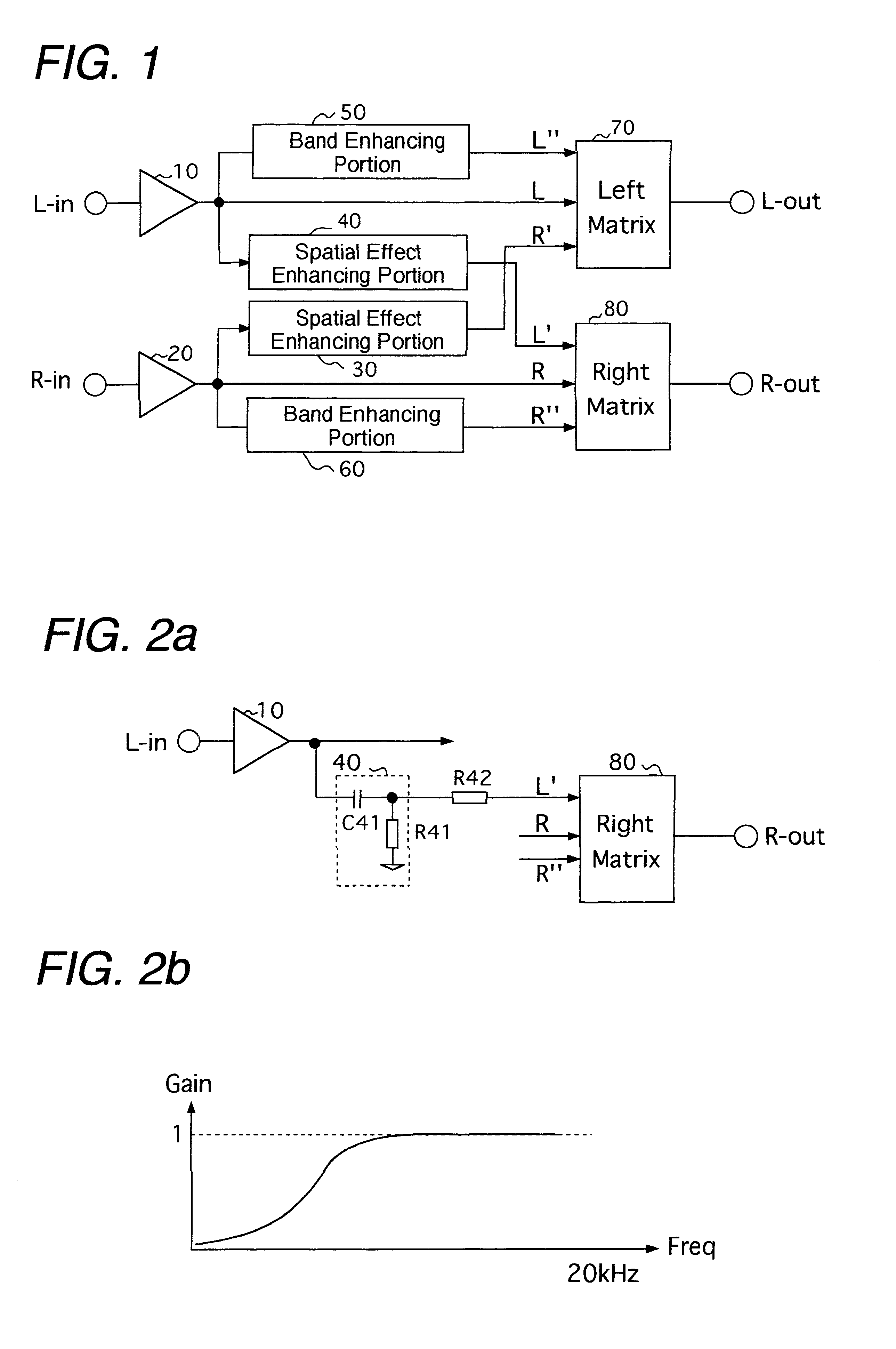
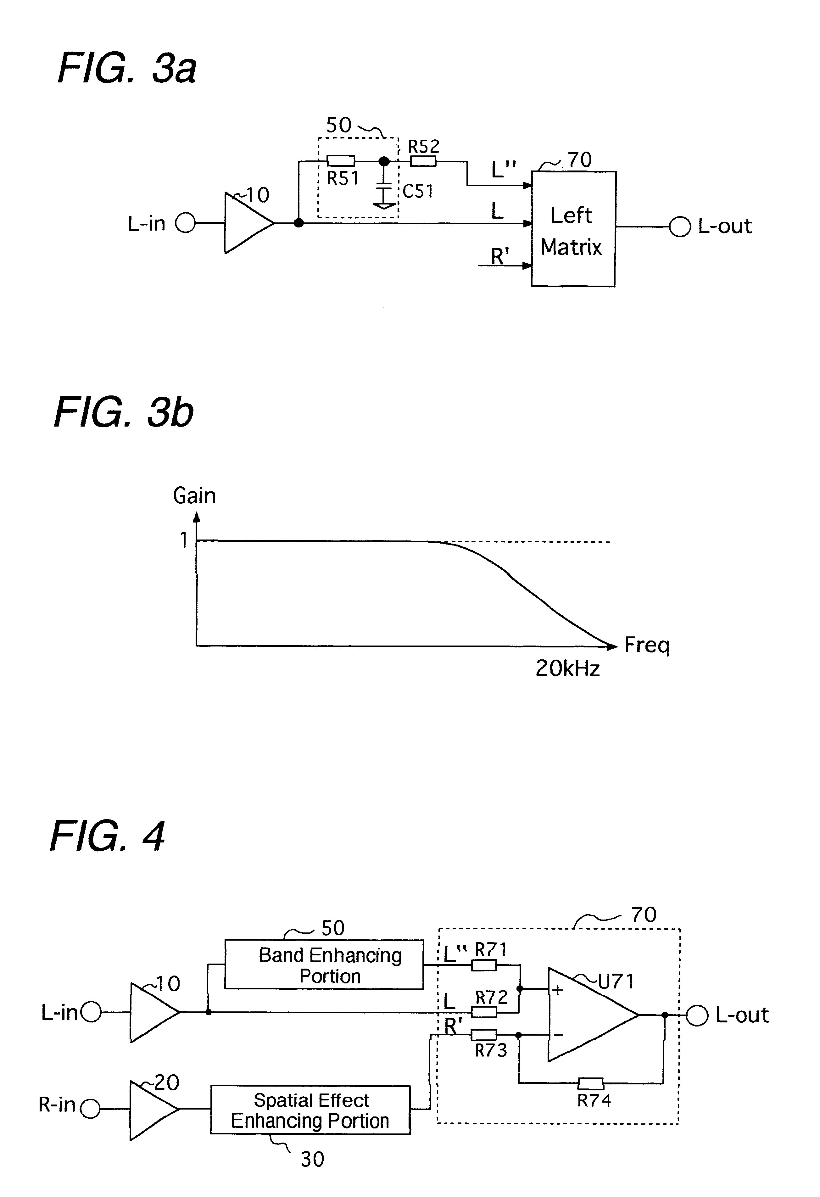
As shown in FIG. 1, the system of the first embodiment comprises a spatial effect enhancing portion (30) (40), a band enhancing portion (50) (60) and a channel matrix portion (70) (80) in each of left and right signal lines. In the spatial effect enhancing portion (30) (40), the left and right input signals (L-in) (R-in) are inputted, respectively, to produce a signal for enhancing a spatial effect and a directivity of sound in a reproduced sound; in the band enhancing portions (50) (60), the left and right input signals (L-in) (R-in) are inputted, respectively, to generate a signal for enhancing the signal components of the middle and low frequency ranges of an original sound; an...

second embodiment

FIG. 9 is a block diagram depicting the construction of the circuits provided after the matrix portion in the second embodiment; FIG. 9(a) is a block diagram representing the circuit structure of the second band enhancing portions in detail; FIG. 9(b) is a graph showing the characteristic of the output signal of the second band enhancing portion.

As explained above, according to the invention, a sound which is well balanced sense in the lower, middle and higher frequency ranges and has a good attendance can be reproduced by the matrix calculations conducted in the matrix portions (70) and (80). However, according to the second embodiment, it is constituted such that the outputs of the matrix portions are filtered again by the second band enhancing portions (90) (100), which are provided in the downstream side of the matrix portions, so that the particular frequency range can be further enhanced. According to the second embodiment, the system can be suitably applied to special kind of...


PUM


Abstract

A system for improving a spatial effect of stereo sound or encoded sound when producing three dimensional image sound signals from signals of stereo channel includes a spatial effect enhancing portion where a signal for enhancing spatial effect and directivity of sound is produced, a band enhancing portion where a signal for enhancing a signal component of the stereo channel signal in a low frequency range and for maintaining the signal component in a middle frequency range is generated, and a matrix portion where the output signal of the spatial effect enhancing portion, the output signal of the band enhancing portion and the stereo channel signal are calculated in a matrix manner, so that the spatial effect of sound is improved using a differential component between left and right side channel signals. According to the invention, the spatial effect of sound can be improved without using a complicated circuit construction, the deterioration of S/N ratio is prevented, and the cost performance for realizing a spatial effect of sound is remarkably improved.

Description

1) Field of the InventionThe present invention relates to a system for improving a spatial effect of stereo sound or encoded sound, and particularly relates to a system for improving a spatial effect of stereo sound or encoded sound, e.g. sound processed by Dolby Prologic, AC3, THX or Digital Surround, which is suitably applied to a three dimensional stereo sound image processing technique. According to the invention, a spatial effect in stereo sound or encoded sound and background sound of music are emphasized when a three dimensional image sound is reproduced from a stereo signal using only two speakers; getting a "live" sound effect.2) Related ArtAs related arts for improving the spatial effect of stereo sound, there have been suggested in U.S. Pat. No. 4,748,669 "Stereo Enhancement System" or in U.S. Pat. No. 4,866,774 "Stereo Enhancement and Directivity". In these U.S. patents, a technique to improve the directivity and spatial effect of stereo sound is disclosed. According to ...

Claims


Application Information

Patent Timeline
IPC IPC(8): H04S1/00H04S5/02
CPCH04S1/002
Inventor CHOI, PYUNG
Owner 3S TECH
Why Eureka
Try Eureka