

Temporary soil sheathing apparatus
A support device and soil layer technology, which is applied in construction, excavation, and infrastructure engineering, etc., can solve the problems of shrinking working space, increasing construction costs, and reducing work efficiency, so as to increase working space, reduce material usage, and improve work efficiency. efficiency effect
- Summary
- Abstract
- Description
- Claims
- Application Information
AI Technical Summary
Problems solved by technology
Method used
Image

Examples
Embodiment 1
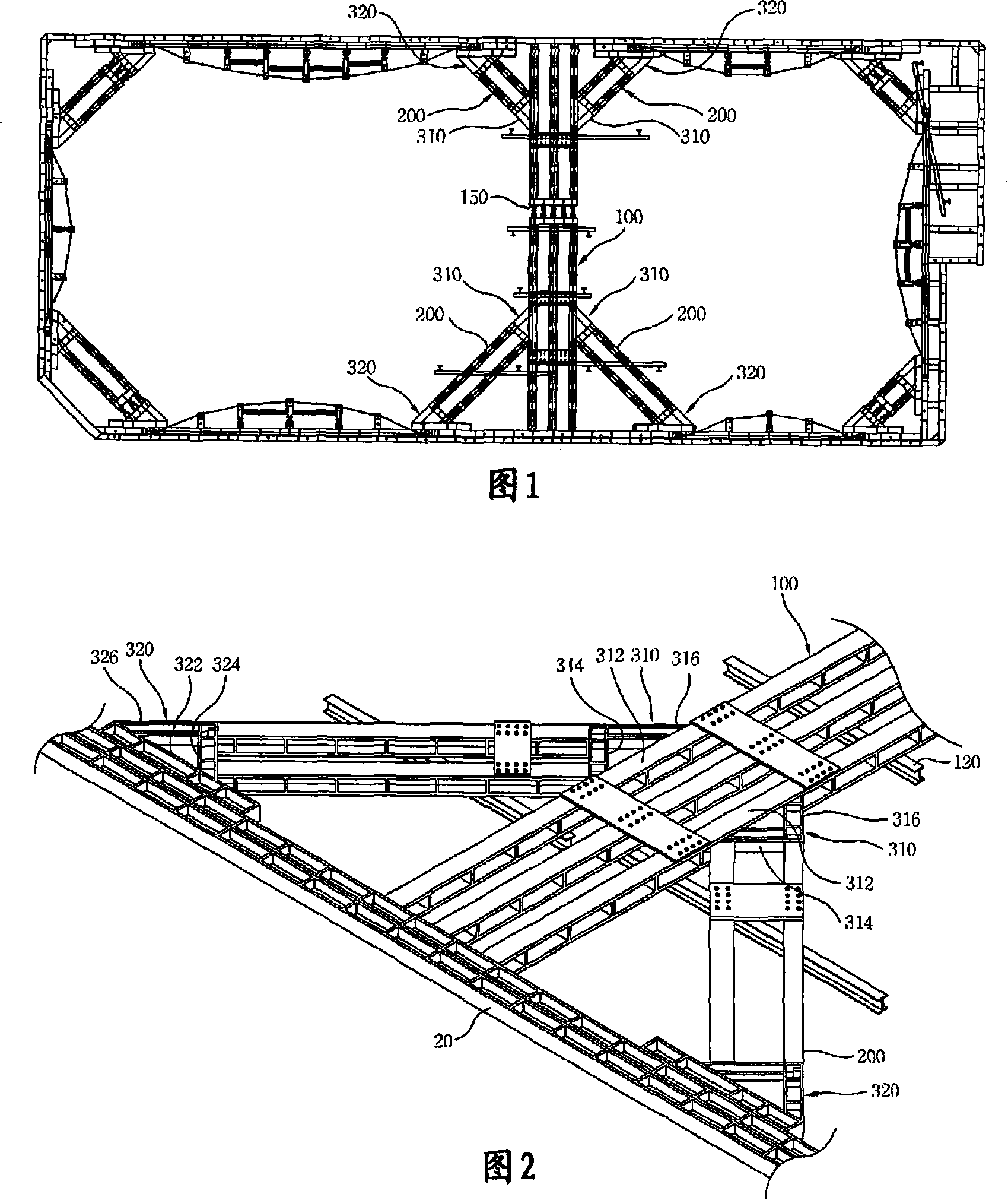
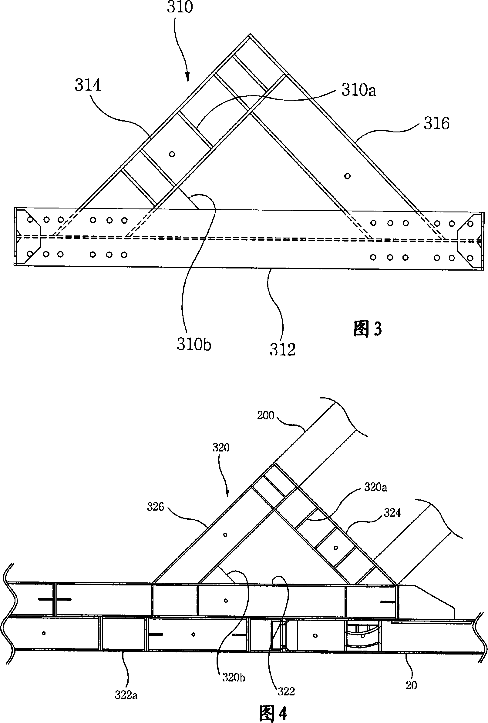
[0042] refer to Figures 1 to 4 , the temporary soil layer support device according to the first embodiment of the present invention includes: a cross brace 20, which is integrally coupled to a retaining wall (not shown), to be vertical to the rectangular area during the excavation work. The excavation parts are installed in a parallel manner and support the earth pressure; a set of intermediate connecting beams 100 traverse along the side of the retaining wall and support the earth pressure transmitted from the retaining wall; The middle coupling beam set 100 and the corresponding cross braces 20 are supported obliquely so as to be connected together with the middle coupling beam set 100 and the corresponding cross braces 20 in a triangular structure.
[0043] More specifically, the intermediate connecting beam group 100 includes a plurality of connecting beams, and has a special structure, wherein each intermediate connecting beam is connected to the cross brace 20 in such a w...
Embodiment 2
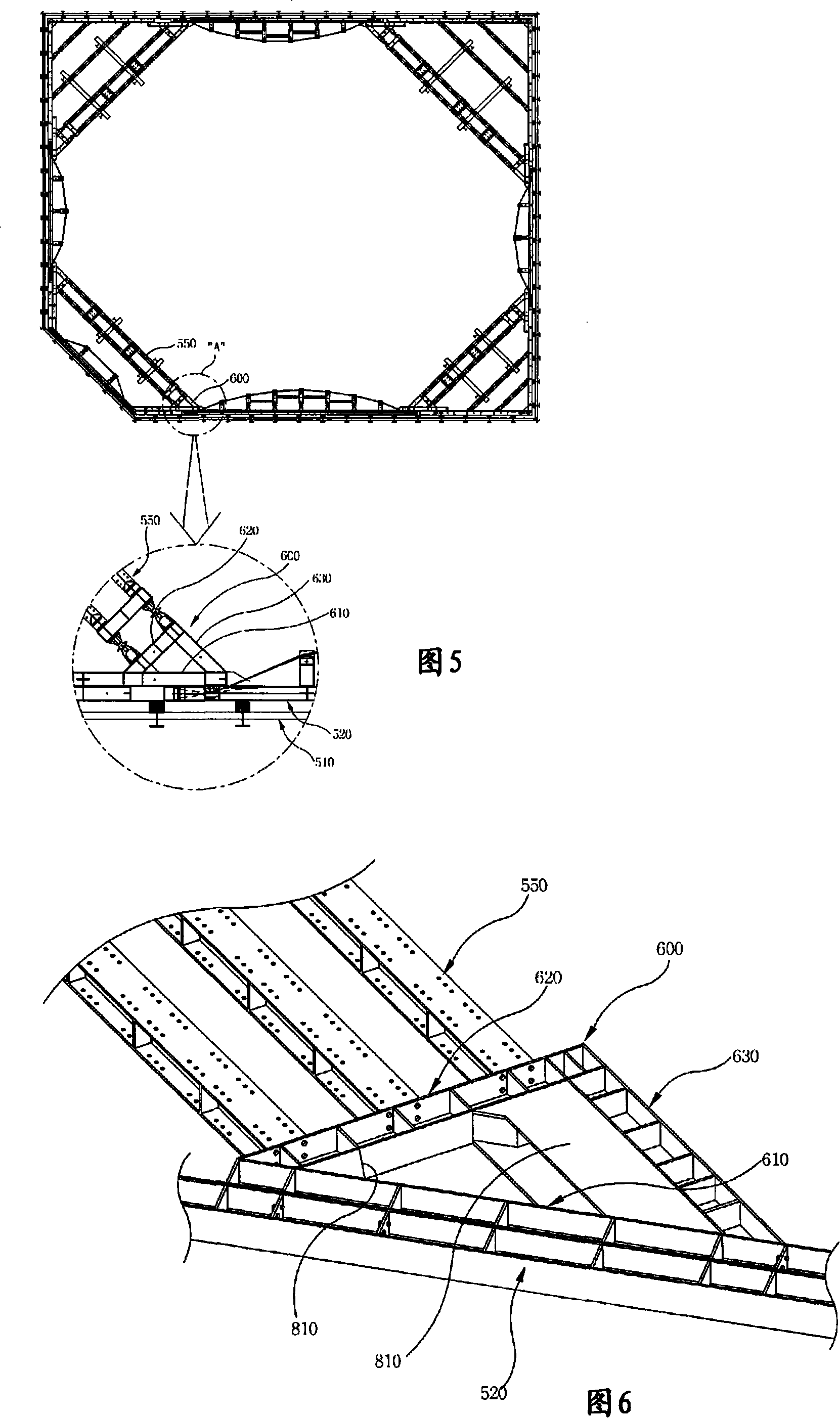
[0063] The temporary soil layer support device according to the second embodiment of the present invention further includes a corner connection structure using the triangular support structure employed in the temporary soil layer support device according to the first embodiment of the present invention. In this case, the temporary soil layer support device can improve the efficiency of space utilization and the ability to withstand earth pressure by simplifying the structure.
[0064] The temporary soil layer support device according to the second embodiment of the present invention further encloses the corner connection structure, which adopts the above-mentioned triangular support structure. refer to Figures 5 to 8 , according to the second embodiment of the present invention, the temporary soil layer support device includes: a support wall 510, which is installed in parallel with the vertical excavation part during the excavation work; integrally coupled to the retaining ...
Embodiment 3
[0082] The temporary soil layer support device according to the third embodiment of the present invention further includes a corner connection structure, which is arranged in a row at each corner and integrated in a truss structure when excavation work for constructing an underground structure is performed. , suitable for uniform transmission of horizontal loads, so that sufficient capacity to withstand bending loads is obtained using coupling beams.
[0083] refer to Figures 9 to 13 , according to the third embodiment of the present invention, the temporary soil support device includes: coupling beams 1100, which are obliquely arranged in rows at each corner when performing excavation work for constructing underground structures, and the two ends are supported supported on the wall 1010; and at least one connecting plate 1200 interconnecting the upper or lower surfaces of adjacent coupling beams 1100 using coupling members.
[0084] More specifically, the connecting plate 120...
PUM
 Abstract
Description
Claims
Application Information