Hydraulic unit for a cylinder head for a combustion engine with a variable valve stroke

A technology of hydraulic units, valve actuators, applied in the direction of valve devices, engine components, machines/engines, etc., which can solve the problems of air bubble inhalation, not reliably avoiding formation, etc.

Active Publication Date: 2009-05-20
SCHAEFFLER TECH AG & CO KG
View PDF0 Cites 4 Cited by
  • Summary
  • Abstract
  • Description
  • Claims
  • Application Information

AI Technical Summary

Problems solved by technology

[0010] From the publication cited at the outset, this problem can only be mitigated to a limited extent even by enlarging the medium-pressure chamber in the direction of the upper part of the housing with corresponding cavities, because even in this case there is still no The formation of gas bubbles in the medium-pressure chamber and the suction of gas bubbles into the expanding high-pressure chamber are reliably avoided

Method used


Image

  • Hydraulic unit for a cylinder head for a combustion engine with a variable valve stroke
  • Hydraulic unit for a cylinder head for a combustion engine with a variable valve stroke

Examples


Embodiment Construction

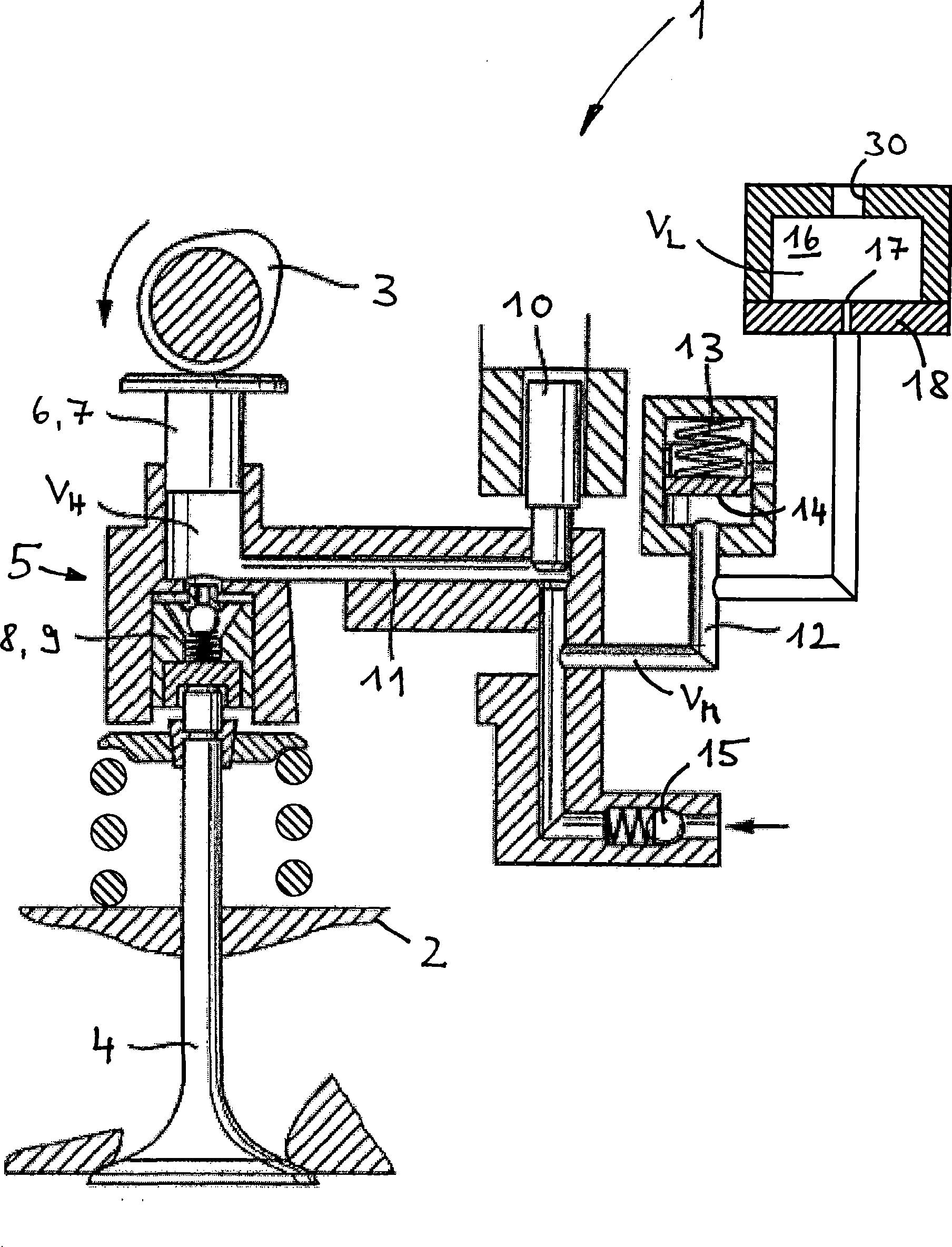
[0025] exist figure 1 The principle structure of the hydraulically variable valve drive 1 and the features pertaining to the invention are disclosed schematically in . To facilitate the understanding of the invention, a main section of a cylinder head 2 of an internal combustion engine is shown, including a cam 3 of a camshaft and a gas exchange valve 4 which is spring-loaded in the closing direction. The variability of the valve actuator 1 is produced by means of a hydraulic unit 5 arranged between the cam 3 and the gas exchange valve 4, the hydraulic unit 5 comprising the following components:

[0026] - the detector unit 6 on the drive side, here in the form of a pump plunger 7 driven by the cam 3;

[0027] - receiver unit 8 on the output side, here in the form of a receiver piston 9 directly actuating the gas exchange valve 4;

[0028] - a controllable hydraulic valve 10, here in the form of an electromagnetic 2-position, 2-way distributing valve;

[0029] - a high pres...


PUM


Abstract

A hydraulic unit (5) for a cylinder head (2) of an internal combustion engine with a hydraulic, variable valve train (1) is provided. In the hydraulic unit, a high-pressure chamber (11), a medium-pressure chamber (12), and also a low-pressure chamber (16) used as a hydraulic medium reservoir are formed. The low-pressure chamber communicates merely via a choke opening (17) with the medium-pressurechamber, wherein the choke opening passes through a separating wall (18) extending between the low-pressure chamber and the medium-pressure chamber.

Description

technical field [0001] The invention relates to a hydraulic unit of a cylinder head of an internal combustion engine with a hydraulically variable valve drive comprising: [0002] at least one drive-side detector unit, [0003] · at least one receiver unit on the output side for actuating the purge valve, [0004] at least one medium-voltage compartment, [0005] at least one high-pressure chamber, which is arranged for transmission between the associated detector unit and the associated receiver unit and can be connected to the associated medium-pressure chamber via an associated hydraulic valve, and [0006] a hydraulic housing having a housing lower part and a housing upper part, [0007] In this case, at least the detector unit, the receiver unit, the high-pressure chamber, the hydraulic valve and the medium-pressure chamber together with the hydraulic housing belong to the hydraulic unit which can be mounted on the cylinder head. Background technique [0008] A hydr...

Claims


Application Information

Patent Timeline
Patent Type & Authority Applications(China)
IPC IPC(8): F01L9/02F01L9/14
CPCF01L2001/34446F01L2820/02F01L9/025F01L9/14F01L13/00
Inventor 马丁·劳赫马库斯·普罗什科
Owner SCHAEFFLER TECH AG & CO KG
Why Eureka
Try Eureka