

Overload prevention device for permanent magnet DC motors
A technology of electric motors and equipment, which is applied to the reduction gear of AC motors, starters of single DC motors, motor generators/starters, etc., and can solve problems such as power consumption and overall system efficiency reduction
- Summary
- Abstract
- Description
- Claims
- Application Information
AI Technical Summary
Problems solved by technology
Method used
Image

Examples
Embodiment Construction
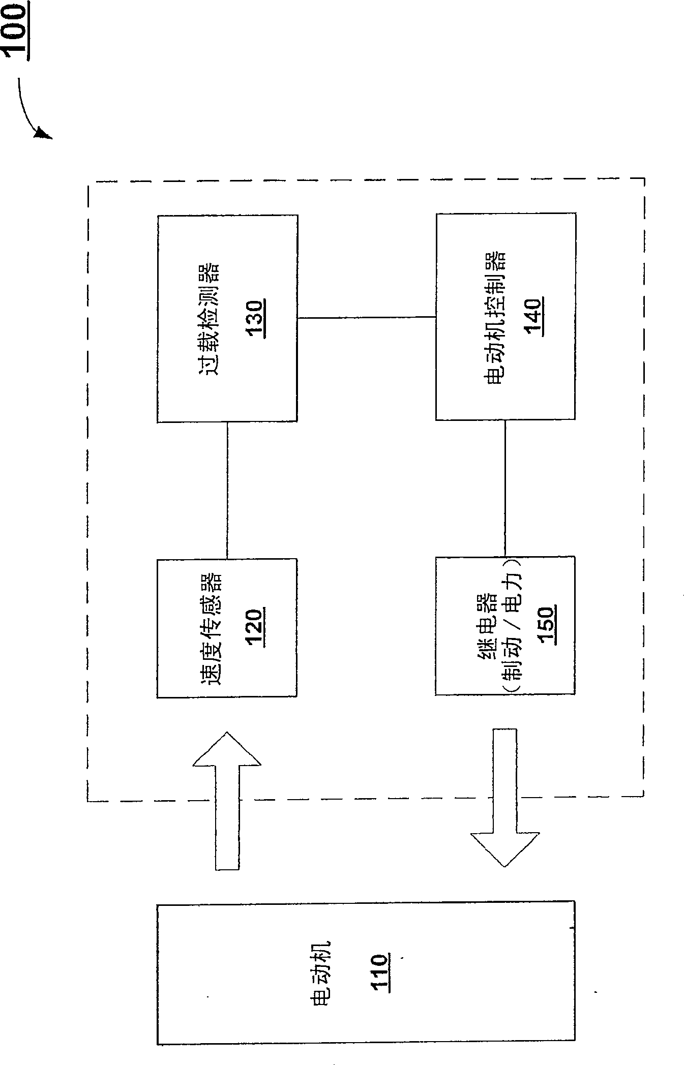
[0012] According to various aspects, there is provided an apparatus, system, method, computer product, computer program, etc. to protect against overload conditions of electric motors, such as permanent magnet DC motors used in linear or rotary actuators. The fundamental parameters of a permanent magnet DC motor are linearly related, i.e. an increase in load torque will result in a proportional decrease in motor speed and a proportional increase in motor input current. Any of the three properties can be measured to predict the status of the other two properties. Because motor speed in a permanent magnet DC motor is inversely proportional to motor current, speed is an accurate predictor of current. Thus, instead of current as an indicator, the speed of the motor (eg, motor RPM, etc.) can be used as an indicator of load. Thus, depending on the speed of the motor and its monitoring, motor overload conditions can be detected and protective measures taken.
[0013] According to e...
PUM
 Abstract
Description
Claims
Application Information