Method for monitoring lubricant distribution system and lubricant distribution system using same

A distribution system and lubricant technology, which is applied in the direction of engine lubrication, distribution devices, lubricating parts, etc., can solve the problems of many oil circuit connections, easy aging oil leakage, and few oil circuit connection ports, etc., to achieve intelligent detection Effect

Inactive Publication Date: 2009-10-21
职子竖
View PDF2 Cites 22 Cited by
  • Summary
  • Abstract
  • Description
  • Claims
  • Application Information

AI Technical Summary

Problems solved by technology

Its disadvantages are: it is impossible to know which lubrication point is blocked; the dynamic seal at the indicator rod of the distributor is prone to aging and oil leakage
Its disadvantages are: the blockage of one lubrication point often affects all six lubrication points of the same single-line progressive distributor; there are too many oil circuit connections in ea...

Method used


Image

  • Method for monitoring lubricant distribution system and lubricant distribution system using same
  • Method for monitoring lubricant distribution system and lubricant distribution system using same
  • Method for monitoring lubricant distribution system and lubricant distribution system using same

Examples


Embodiment 1

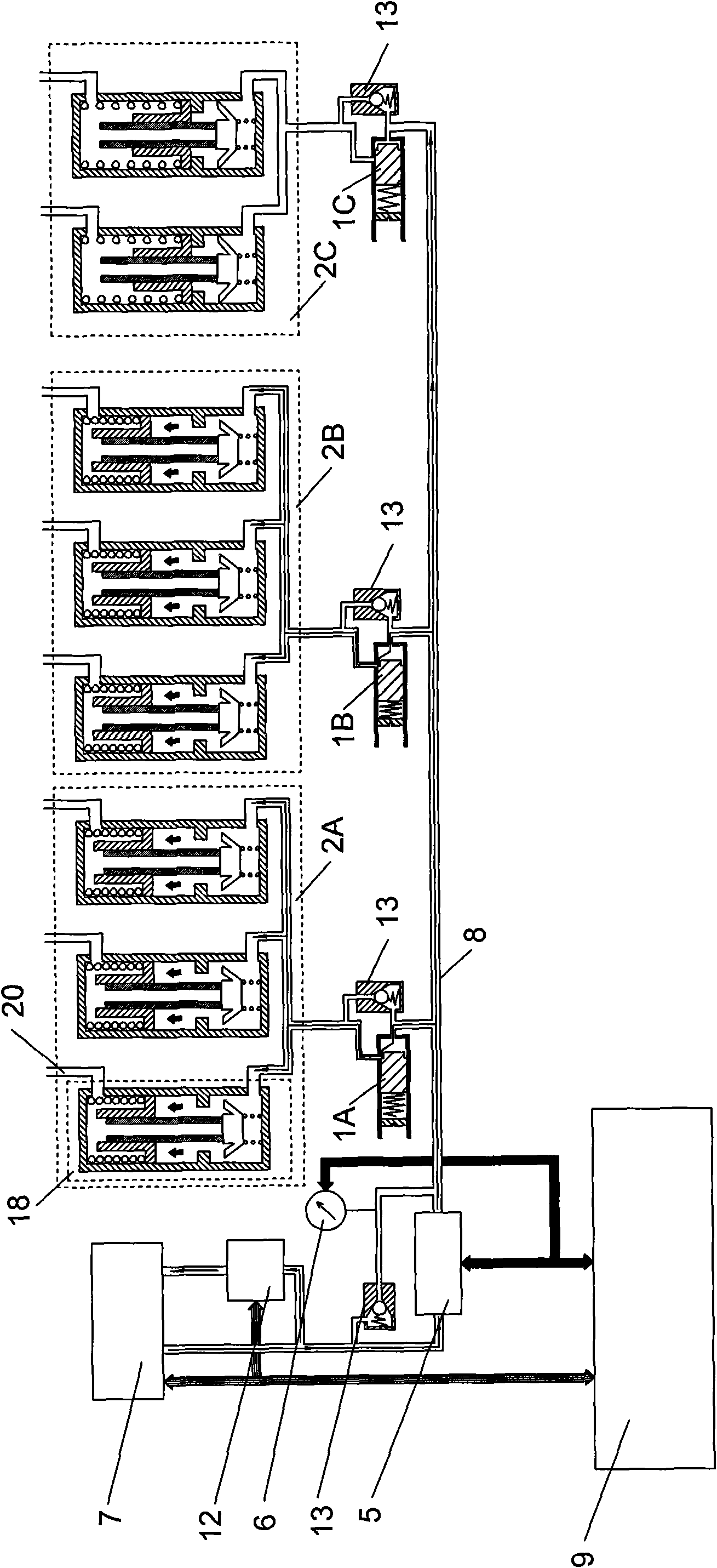
[0046] The monitoring method of the present invention means that a flow sensor and a pressure sensor I are arranged upstream of the distributor of the lubricant distribution system, and each distributor is connected with a pressure control valve with different parameter values. In this embodiment, the control fluid for controlling the pressure control valve is the lubricant itself, and the pressure control valve is a two-position two-way on-off type pressure control valve. When the pressure value of the lubricant output by the oil pump station 7 is greater than the opening pressure value of a certain pressure control valve connected to the distributor, the pressure control valve is opened, the oil supply pipe 8 and the inlet of the distributor are connected, and the lubricant is distributed from the When the output pressure of the oil pump station continues to increase, the pressure control valves with greater pressure parameters are opened one after another. Conversely, when ...

Embodiment 2

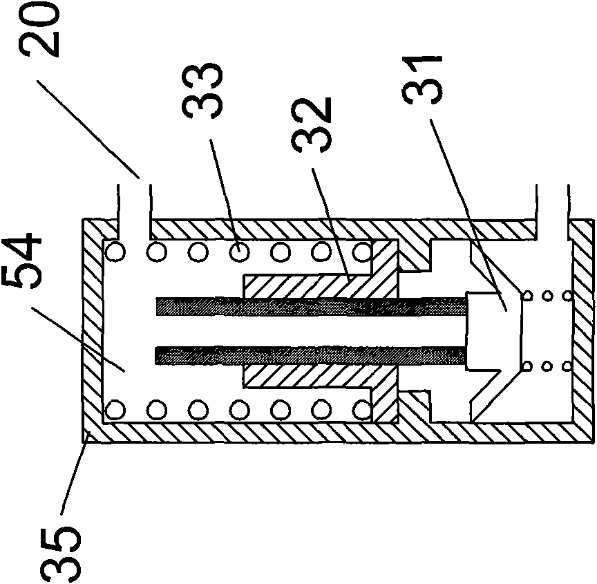
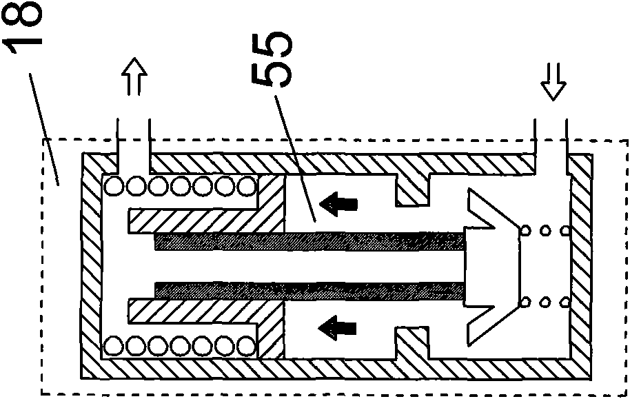
[0057] Such as Figure 8 As shown, the difference between this embodiment and Embodiment 1 is that in this embodiment, the distributors in the lubricant distribution system are divided into two groups: the first group includes three distributors 2A, 2B, 2C, and the second group includes Two distributors 2D, 2E, each distributor in the second set is equipped with a pressure control valve 1D, 1E. In this embodiment, each distributor still adopts a single-line volumetric distributor, the first group of distributors is the same as that described in Embodiment 1, and in the second group of distributors, each distributor includes three volume units 18 , each volume unit 18 is also of 5ml specification, that is, during one oil pressure rise process, each volume unit 18 outputs 5ml of lubricant to the corresponding outlet 20 .

[0058] In addition, a flow sensor and a pressure sensor are arranged upstream of each group of distributors, and the output end of the flow sensor is connect...

Embodiment 3

[0063] The difference between this embodiment and Embodiment 1 is that in this embodiment, a plurality of two-position two-way on-off pressure control valves are respectively located at the outlets of the distributors 2A, 2B, and 2C, and the distributors 2A, 2B, and 2C have Eight outlets, so a total of eight pressure control valves are required. In this way, when the pressure value output by the oil pump station 7 is greater than the rated pressure value of the pressure control valve of the corresponding lubrication point, the pressure control valve can be opened, so that the lubricant flows out to the lubrication point through the volume unit and the pressure control valve.

[0064] The continuous casting machine uses this lubricant distribution system. Generally, the distributor of each working section is a group, and the corresponding flow sensor and pressure sensor are matched.

[0065] Other technical characteristics are identical with embodiment 1.


PUM


Abstract

The invention discloses a method for monitoring a lubricating system and a lubricating system using the same. The method comprises the following steps that: when the pressure or pressure change of the control fluid of a pressure control valve is matched with the pressure property of a pressure control valve arranged at the lower reach of a lubricant supply source arranged in the lubricating system, the pressure control valve acts; according to the flow direction of lubricant, a flow sensor is arranged at the upper reach of the pressure valve for acquiring the flow value of passing lubricant; a pressure sensor I is arranged on the path of the control fluid of the pressure control valve for acquiring the pressure value of the control fluid; the acquired flow value of the lubricant and the acquired pressure value of the control fluid are transmitted to an intelligent controller; and the intelligent controller stores a comparative judgment program, and judges whether a lubricated point is blocked and determines the position of a blocked lubricated point. The method saves the arrangement of a detection element on a distributor, uses few oil path connectors, can point out exact position of the blocked lubricated point, and realizes the intelligent detection of the position of a lubricated point failure.

Description

technical field [0001] The invention relates to a monitoring method for a lubricant distribution system, in particular to a method for pointing out the position of a blocked lubrication point in a lubricant distribution system or the position of a distributor where a blocked lubrication point is located, without the need of setting detection elements on the distributor A method of monitoring and involving a lubricant dispensing system using the method. Background technique [0002] At present, the two-line lubrication method is widely used in continuous casting machines in steel mills. Its advantages are: each working section has only two oil circuit connections; each lubricating point is independent of each other, and the blockage of one lubricating point will not affect other lubricating points. Its disadvantages are: it is impossible to know which lubricating point is blocked; the dynamic seal at the indicator rod of the distributor is prone to aging and oil leakage. If...

Claims


Application Information

Patent Timeline
IPC IPC(8): F16N29/02F16N25/00G05B19/048G05D16/04
Inventor 职子竖姚建青马秀叶孟祥伟李祖森夏根华夏华刚沈根荣崔小军
Owner 职子竖
Why Eureka
Try Eureka