Pneumatic anchor rod hammer drill

A technology of rock drills and air legs, applied in the field of rock drills, can solve the problems of difficult control, inconvenient operation, and difficult control of the staff, and achieve the effect of easy control, convenient operation, and strong vibration reduction

Active Publication Date: 2009-11-11
青岛达邦钻机有限责任公司
View PDF1 Cites 4 Cited by
  • Summary
  • Abstract
  • Description
  • Claims
  • Application Information

AI Technical Summary

Problems solved by technology

[0003] The deficiencies of this improved structure are: 1. Since the variable speed gearbox and the wind motor are arranged on the head side of the original body, away from the support axis of the legs of the rock drill, the entire weight is concentrated on the head of the rock drill, so when drilling,

Method used


Image

  • Pneumatic anchor rod hammer drill

Examples


Embodiment Construction

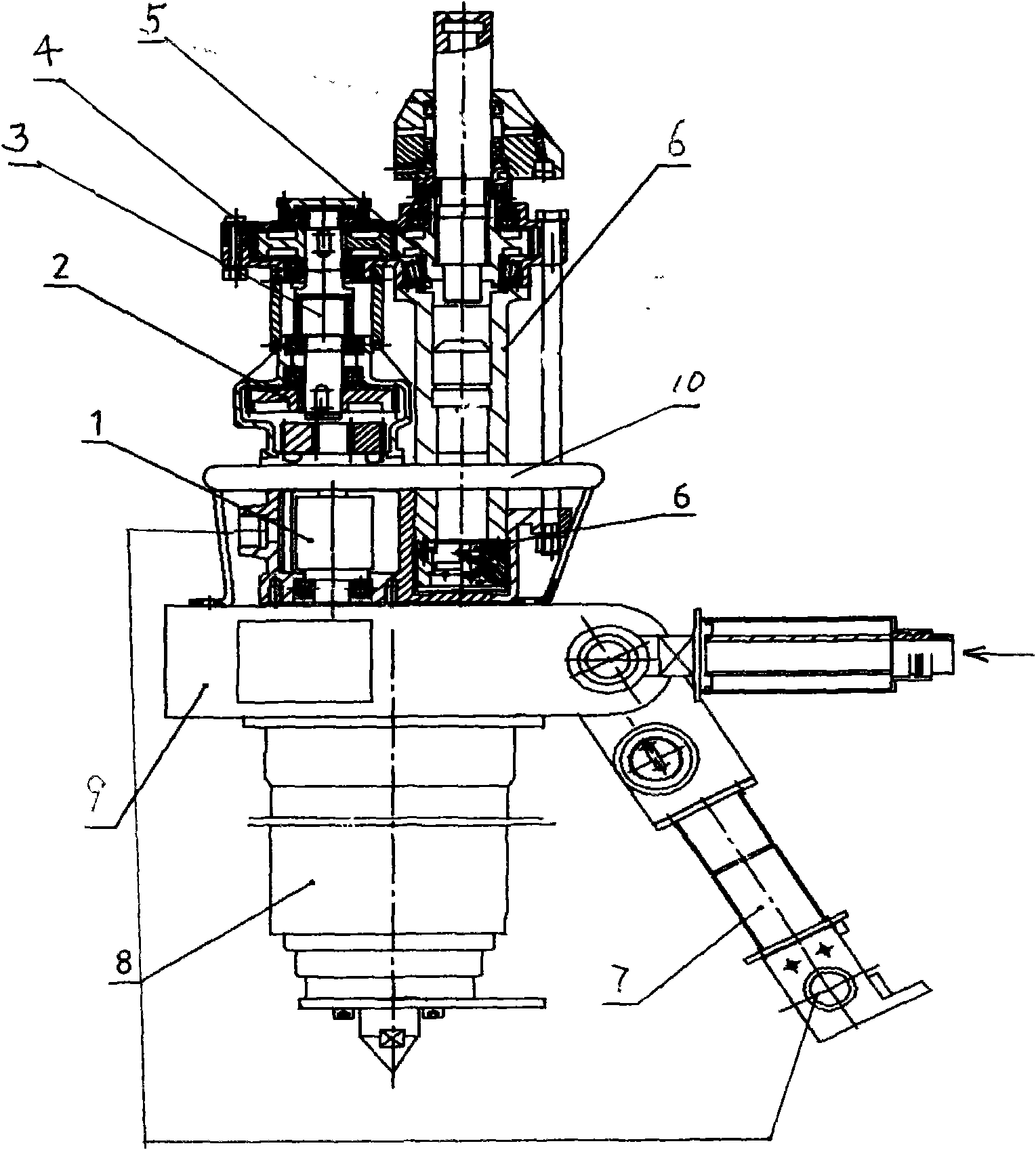
[0010] Such as figure 1 As shown, the present invention includes a rock drill body composed of a rock drill shell, an impact part 6 in the shell, an air leg 8, and an operating arm 7, and a rotating part composed of a speed change gearbox 2 and an air motor 1. The fiber tail sleeve of the impact part 6 A gear 5 is processed on the top, and an extension shaft 3 is connected to the power output shaft of the transmission gearbox 2, and a transmission gear 4 is installed on the extension shaft 3, and the transmission gear 4 meshes with the fiber tail sleeve gear 5; the rotating part and the rock drill casing pass through The connecting and fixing parts 10 are jointly fixed on a machine body seat 9 to form a whole rock drilling machine; 3. The supporting axis of the air leg 8 is arranged on the center of gravity of the overall weight of the rock drilling machine; on the valve.


PUM


Abstract

The invention discloses a pneumatic anchor rod hammer drill, which is mainly characterized in that a power output shaft of a speed change gear box of the prior rotary impact combination hammer drill is connected with a lengthened shaft on which a transmission gear is arranged, and the transmission gear is meshed with a fiber tail sleeve gear; a rotating part and a shell of the hammer drill are corporately fixed on a drill body seat to form a hammer drill whole; a support axis of an air leg is arranged on a gravity line of the weight of the hammer drill whole; and an air inlet pipe of an air motor is directly connected to a valve of an operating arm. The pneumatic anchor rod hammer drill realizes downward shift of the weight of the rotating part, avoids the top-heavy phenomenon, improves the integral stability, avoids direct impact, reduces strong shock during working, and is convenient for a worker to operate.

Description

technical field [0001] The present invention relates to rock drilling machines. Background technique [0002] The rock bolter is a device used for drilling bolt holes in mine roadway support. The technology relevant to this application is the rotary impact combined rock bolt drill disclosed in Chinese Patent Publication No. CN2864065. Its main structure is improved on the basis of the original pneumatic rock drill. The wooden body of the rock drill composed of air legs and control arms, the improved structure of the rotary impact combined rock bolt drill disclosed by the publication number CN2864065 is mainly to increase the rotating part. One side of the shell of the rock drill is connected to a variable speed gearbox, and a pneumatic motor is installed at the lower part of the variable speed gearbox. In addition, the air motor is controlled by an independent valve to enter the wind. [0003] The deficiencies of this improved structure are: 1. Since the variable speed ge...

Claims


Application Information

Patent Timeline
IPC IPC(8): E21B6/00E21B15/00E21D20/00
Inventor 鲍伟赵锦桥宋立新孙文进王洪立
Owner 青岛达邦钻机有限责任公司
Why Eureka
Try Eureka