Detection method and device for bottom thread of computer embroidering machine

A thread detection and computer technology is applied in the field of bottom thread detection of computerized embroidery machines, which can solve the problems of inability to distinguish bottom thread and upper thread breakage, inability to detect bottom thread breakage, and high processing cost of bobbins, achieving simple structure and easy adjustment. , The effect of low cost of electronic control

Active Publication Date: 2010-01-06
BEIJING DAHAO TECH
View PDF1 Cites 3 Cited by
  • Summary
  • Abstract
  • Description
  • Claims
  • Application Information

AI Technical Summary

Problems solved by technology

[0006] 1. The sensitivity is not high. In some cases, although there is no bottom thread, because the needle moves with the upper thread, the upper thread is still rotating with the winding wheel for detection of the bottom thread, so the chopping wheel also rotates, making the bottom thread The output pulse of the optocoupler on the detection board is almost constant, so the bottom thread detection board cannot detect whether the bottom thread is broken;
[0007] 2. It is impossible to distinguish whether the bottom thread or the upper thread is broken;
[0008] 3. Relevant mechanical processing requirements are relatively high, and installation is more troublesome
[0009] 4. If the winding wheel does not rotate smoothly or does not rotate, it will affect the break detection and alarm function
[0010] 5. Using the bottom line detection board, since each needle position corresponds to an optocoupler, the cost of electric control is relatively high
[0011] 6. The processing cost of the winding wheel is relatively high

Method used


Image

  • Detection method and device for bottom thread of computer embroidering machine
  • Detection method and device for bottom thread of computer embroidering machine
  • Detection method and device for bottom thread of computer embroidering machine

Examples


Embodiment Construction

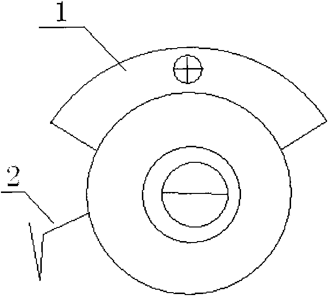
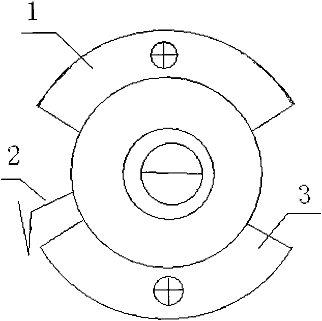
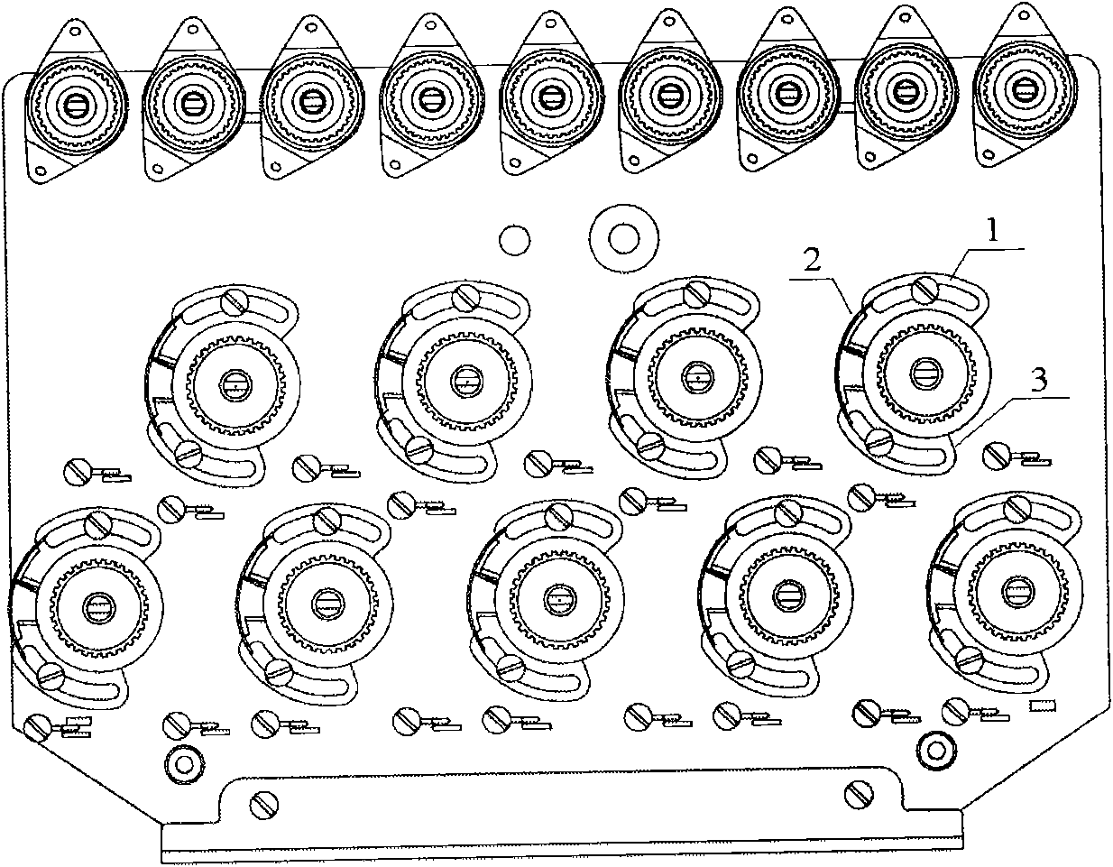
[0027] This example is a nine-needle thread clamping seat. A side thread detection contact 1 is provided above the movement track of the metal thread take-up spring 2 of each thread clamping seat, and a bottom thread detection contact 3 is provided below. Both contacts are metal copper. The column is movably embedded in the circumferential arc-shaped sliding groove, and is relatively fixed with the sliding groove through an adjusting screw, and the positions of the two detection contacts can be adjusted through the adjusting screw.

[0028] When the thread take-up spring is released and reset to the top by the upper thread, it can touch the upper thread detection contact 1, and when the movement range reaches the maximum, it can touch the bottom thread detection contact 3 below.

[0029] The front and back sides of the two detection contacts are conductive, the wire take-up spring is in contact with the front part of the contact, the rear part of the contact is electrically con...


PUM


Abstract

The invention relates to a detection method and device for bottom thread of a computer embroidering machine, utilizing the motion amplitude of a thread take-up spring on a tension seat to judge the thread break condition; work is judged to be normal when the motion amplitude of the thread take-up spring can reach the maximum value, an upper thread is judged to be broken when the motion amplitude of the thread take-up spring is zero, and the upper thread is judged not to be broken but a bottom thread to be broken when the motion amplitude of the thread take-up spring only can reach an intermediate value between the maximum value and the minimum value. The device of the invention is provided with an upper thread detection contact above the thread take-up spring of the tension seat, and a bottom thread detection contact is arranged below the thread take-up spring; the thread take-up spring, the upper thread detection contact and the bottom thread detection contact are electrically connected with a thread broken alarm circuit respectively so as to send an electric connection signal of the upper thread detection contact, the bottom thread detection contact and the thread take-up spring to the thread broken alarm circuit. The invention has the advantages of high sensitivity, simple structure, easy processing and installation, low requirement, low electronic control cost and reliable work and can distinguish whether the upper thread is broken or the bottom thread is broken.

Description

technical field [0001] The invention belongs to an embroidery machine, and in particular relates to a method and a device for detecting a bottom line of a computerized embroidery machine. Background technique [0002] In computerized embroidery machines, thread breakage detection is an important function. It is mainly used to detect whether the upper thread and the bottom thread are broken during the embroidery process. Once the thread breaks, it will immediately alarm. [0003] Most of the existing computerized embroidery machines have upper thread detection function. The main method is to judge the upper thread through the thread take-up spring on the thread clamp seat. Reset, so most of the existing equipment is provided with a copper column contact above the thread take-up spring. Once it is detected that the thread take-up spring touches the upper contact, it is judged that the upper thread is broken. [0004] It is more difficult to judge the broken thread of the bot...

Claims


Application Information

Patent Timeline
Patent Type & Authority Applications(China)
IPC IPC(8): D05C13/02
Inventor 杨宪礼肖斌
Owner BEIJING DAHAO TECH
Why Eureka
Try Eureka