
Novel fluid engine
An engine and fluid technology, applied in the direction of engines, engine components, wind engines, etc., can solve the problems of device manufacturing, high use cost, high power consumption, complex structure, etc., and achieve the effect of reducing manufacturing and use costs and exempting power control
- Summary
- Abstract
- Description
- Claims
- Application Information
AI Technical Summary
Problems solved by technology
Method used
Image

Examples
Embodiment
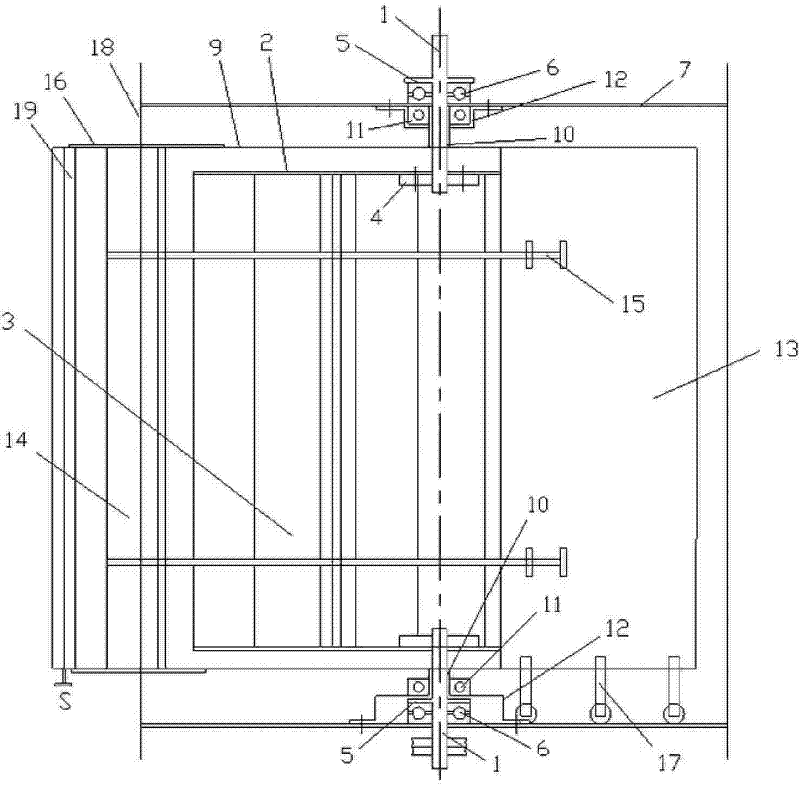
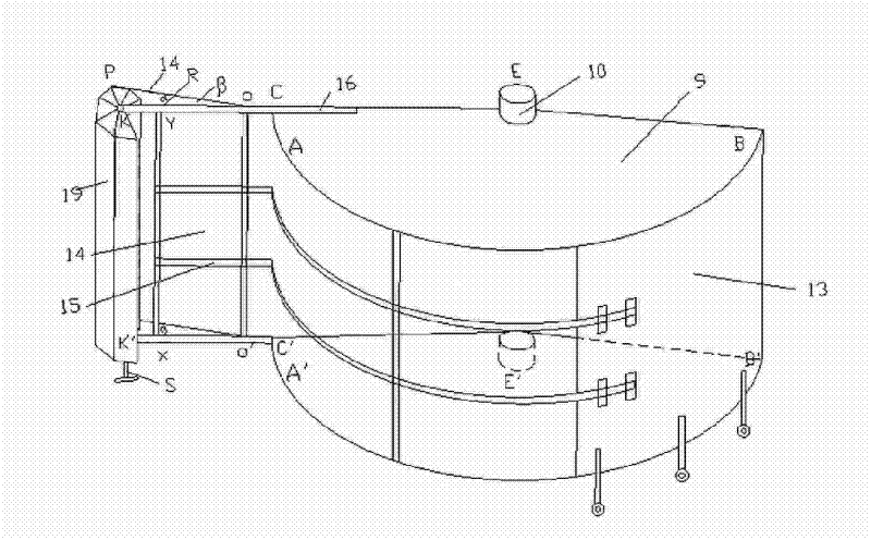
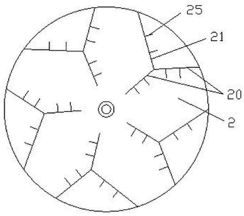
[0030] The product structure features embodied by the technical solution of the present invention are generally divided into two parts: the main body structure of the rotating body and the vertical arc-shaped spoiler moving system on the outer circumference of the rotating body controlled by the wind and guided by the tail rudder. However, considering the convenience of structural installation, it should be divided into the assembly of main components, that is, the processing of the rotating body and the tail rudder tilt adjuster 19, the frame structure, the vertical arc baffle 13 and the support plate 9, and finally the assembly of the whole structure.
[0031] Assembly of rudder pitch adjuster components:
[0032] The tail rudder inclination adjuster 19 is installed at the rear of the tail rudder 14. First, the plane pp'oo' of the tail rudder 14 is made into a stable plane with a small angle iron, and the plane of the tail rudder 14 is made of a 0.5mm galvanized sheet. Insta...
PUM
 Abstract
Description
Claims
Application Information