Clutch rotating short-circuit grounding device

A grounding device and a rotating technology, which is applied in the direction of connection, circuit, conductive connection, etc., can solve the problems of inconvenient operation, poor safety, easy to fall off, etc., and achieve the effect of low production cost, easy operation and high safety performance

Active Publication Date: 2013-03-13
STATE GRID CORP OF CHINA +2
View PDF5 Cites 0 Cited by
  • Summary
  • Abstract
  • Description
  • Claims
  • Application Information

AI Technical Summary

Problems solved by technology

[0008] The present invention aims at the short circuit grounding device in the prior art, which is easy to fall off, poor in safety and inconvenient to operate, and provides a clutch rotating short circuit grounding device to solve the above problems

Method used


Image

  • Clutch rotating short-circuit grounding device
  • Clutch rotating short-circuit grounding device
  • Clutch rotating short-circuit grounding device

Examples


Embodiment 1

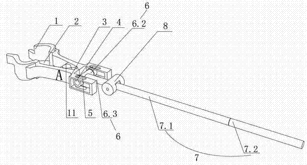
[0037] Such as Figure 2-6As shown, the clutch rotation type short-circuit grounding device of the present invention includes a wire end clamp A and a handle 7. The wire end clamp A includes a pair of splints 1 connected to the steering shaft by means of a support piece 11 and an arc-shaped engagement 2 is provided on the upper part. The support piece 11 A spring is wound around the rotating shaft 12, and the two ends of the spring lean against the inner sidewalls of the two splints 1; the tail part A of the wire end clamp is provided with a pairing module 3, and a movable nut 4 is arranged in the pairing module 3, and the movable nut 4 passes through The screw rod is connected with the movable piece 5 arranged on the pair module 3, the movable nut 4 can rotate laterally along the screw rod, and the movable piece 5 can slide on the pair module 3; Tube 6.3, rotating rod 6.4, side tube 6.5, the end of guide tube 6.3 is connected with cover tube 6.2, side tube 6.5 is hollow, it c...

Embodiment 2

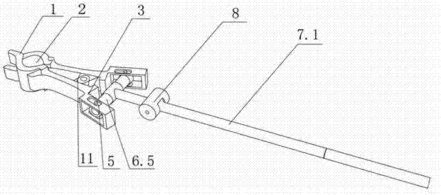
[0041] Such as Figure 7-8 As shown, the difference from Embodiment 1 is that the inner side wall of the one splint 1 is also provided with a depressing tongue 13, which is arranged between the rotating shaft 12 and the arc-shaped bite 2, and the other splint 1 is correspondingly A tongue depressing through hole is provided. The function of the depressing tongue 13 is that when the wire end clamp A is in the open state, the depressing tongue 13 is used to resist the wire end clamp A, so as to avoid the force of the spring to make the telescopic rod 6.1 move back. When it is necessary to loosen the splint 1 for clamping, the pressing tongue 13 contacts the wire, and the wire end clamp A can be released. The remaining technical principles are the same as in Embodiment 1.

Embodiment 3

[0043] The difference from Embodiment 1 is that the telescopic rod 6.1, the rotating rod 6.4, and the grip rotating rod 7.3 are threaded as a whole, and the rest of the operation methods are the same as in Embodiment 1.


PUM


Abstract

The invention discloses a clutch rotating short-circuit grounding device. The clutch rotating short-circuit grounding device comprises a wire-end cable clamp (A) and a holding rod (7), wherein the wire-end cable clamp (A) comprises a pair of clamping boards (1) which are in rotary connection with each other through a rotating shaft, and the upper part of each clamping board (1) is provided with an arc-shaped occlusion opening (2). The clutch rotating short-circuit grounding device is characterized in that the tail end of the wire-end cable clamp (A) is provided with a pair of modules (3) which are internally provided with movable nuts (4); each movable nut (4) is movably connected with the corresponding module (3) and can transversely rotate and slide in the corresponding module (3); a telescoping mechanism (6) is firmly connected to the movable nuts (4) and is connected to the holding rod (7); and the holding rod (7) is provided with an operating mechanism controlling the expansion of the telescoping mechanism (6). The clutch rotating short-circuit grounding device has the advantages of being high in safety performance, and capable of avoiding the automatic falling of the wire-end cable clamp as the wire-end cable clamp is manually controlled to clamp or release a wire.

Description

technical field [0001] The invention relates to a safety tool or appliance for overhauling electric power, in particular to a clutch-rotating short-circuit grounding device. Background technique [0002] In existing short-circuit grounding devices, such as figure 1 The grounding wire 100 shown is a safety tool used to temporarily ground the power equipment that has been powered off when the power equipment is overhauled. The induced electric influence generated, in order to prevent the occurrence of electric shock accidents caused by the staff. Installing a grounding wire is a necessary safety technical measure to change the power equipment from the operating state to the maintenance state. The grounding wire 100 is connected to the wire and the earth by means of the wire end wire clamp 200 and the grounding end wire clamp 300 respectively. However, in the prior art The wire end clamp includes a pair of splints 600 connected by rotation shaft 400 and the upper part is prov...

Claims


Application Information

Patent Timeline
Patent Type & Authority Applications(China)
IPC IPC(8): H01R11/14H01R4/48H01R43/00
Inventor 黄景明宋倩怡李杨梁之臻
Owner STATE GRID CORP OF CHINA
Why Eureka
Try Eureka