
Transportable merchandise display unit

Inactive Publication Date: 2005-01-04
TERRY SMITH GROUP
View PDF9 Cites 27 Cited by
  • Summary
  • Abstract
  • Description
  • Claims
  • Application Information

AI Technical Summary

Benefits of technology

An object of the present invention is to provide an improved display structure that requires reduced expenditure in terms of man-hours to erect, and one which is capable of being pre-stocked prior to delivery at a retail outlet.
According to an aspect of the present invention, there is provided a transportable merchandise display unit comprising: an outer container containing an inner display case, the inner case being slidable along a predetermined path relative to the outer container through an opening in the top of said outer container, the outer container including retractable display case support means positioned at a predetermined location along said path the support means being urged for movement from a retracted position out of said path to an extended position extending into said path, the inner display case being arranged to hold said support means in its retracted position until it is vertically displaced from an initial transit position inside the outer container to a position beyond said predetermined location where the inner display case projects through said opening, at which instant the support means resiles to the extended position into the predetermined path to provide support for the inner display case at that location and prevent the inner display case from returning under the force of gravity to its initial transit position.

Problems solved by technology

There are disadvantages with these conventional types of manufacturer supplied temporary displays, in that they require complete assembly at the retail site; a task which is often complicated and time consuming, and therefore expensive in terms of man-hours.
Again, this occupies the time and labour of a retail operative.

Method used


Image

  • Transportable merchandise display unit
  • Transportable merchandise display unit
  • Transportable merchandise display unit

Examples


Embodiment Construction

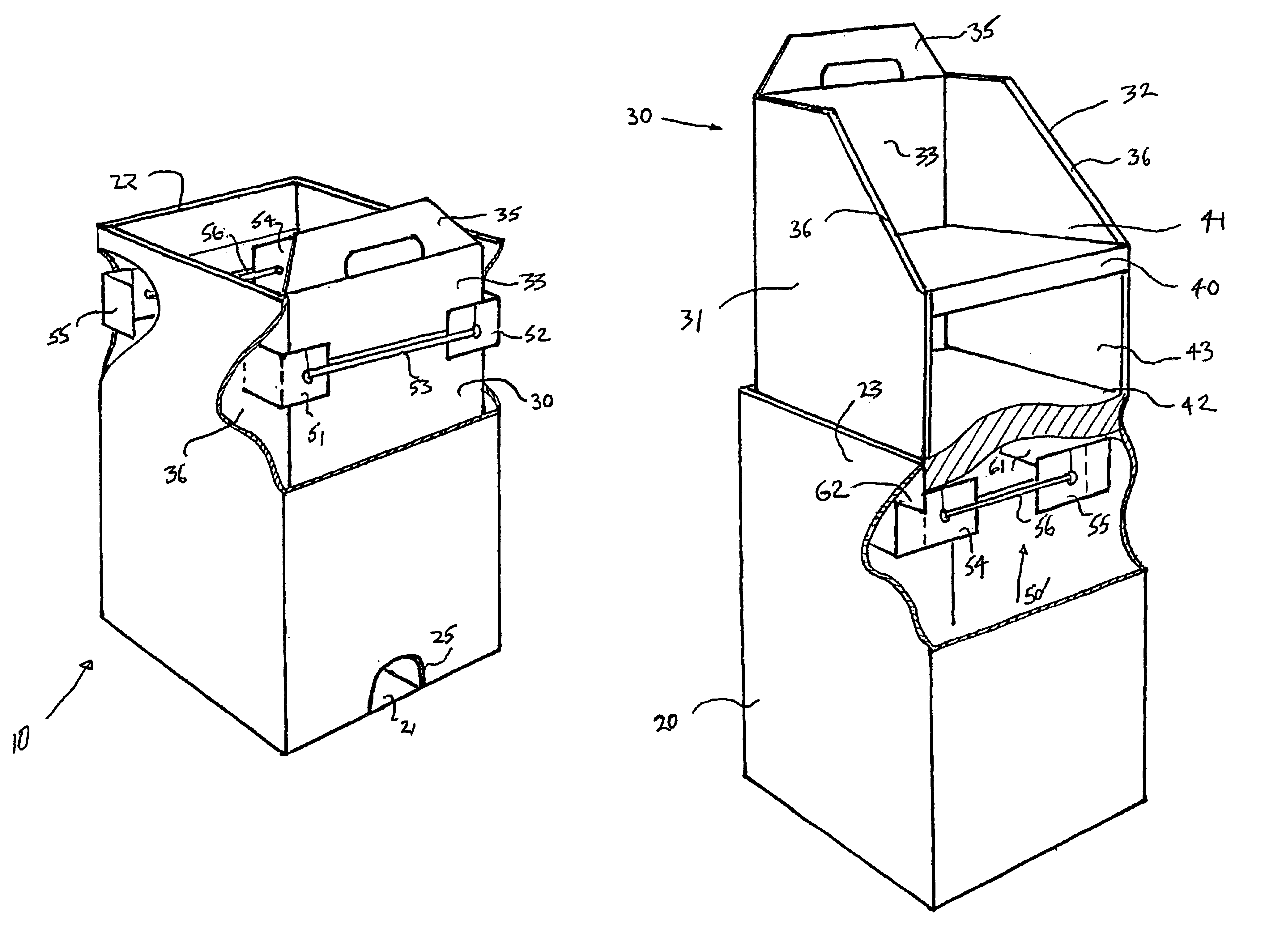
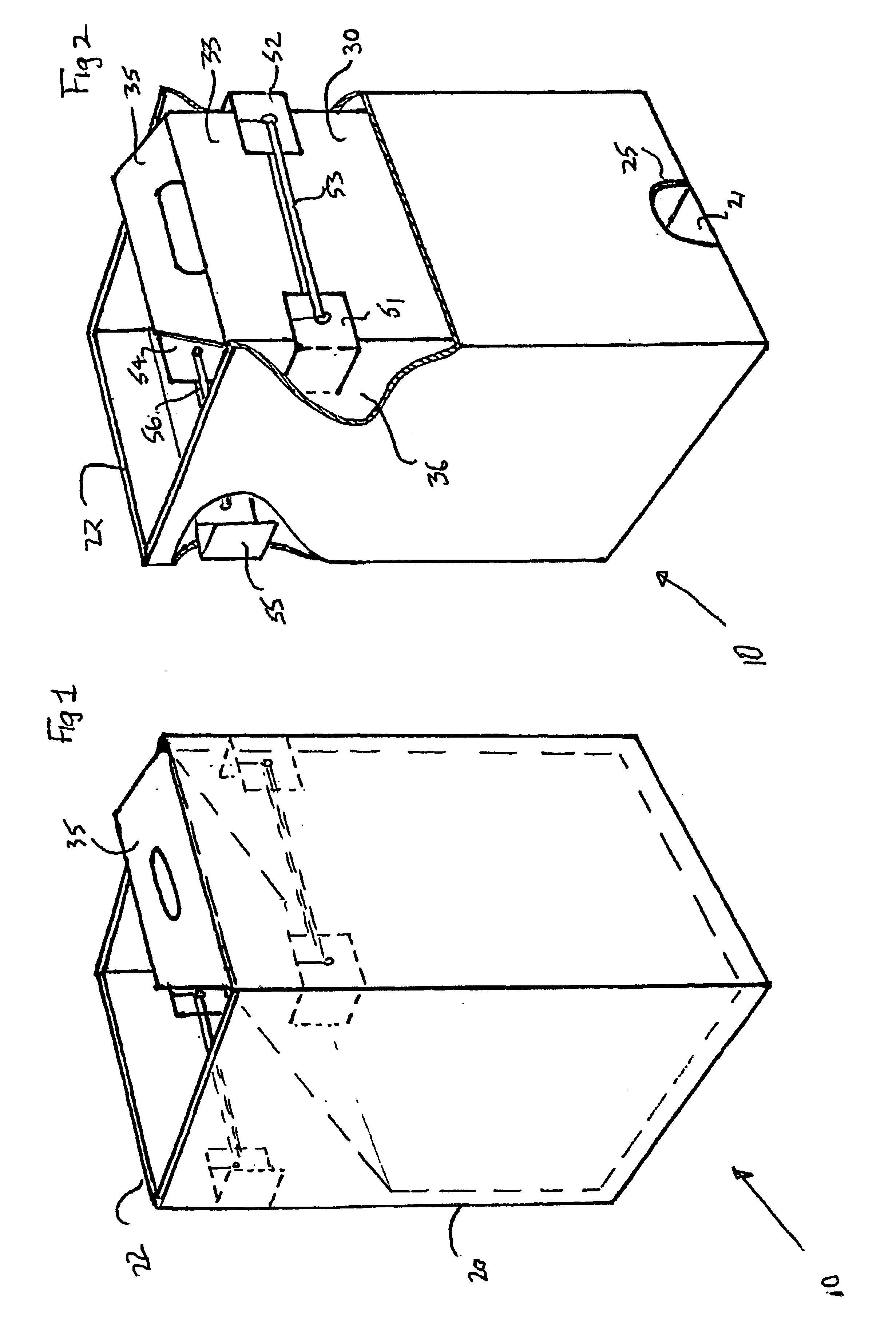
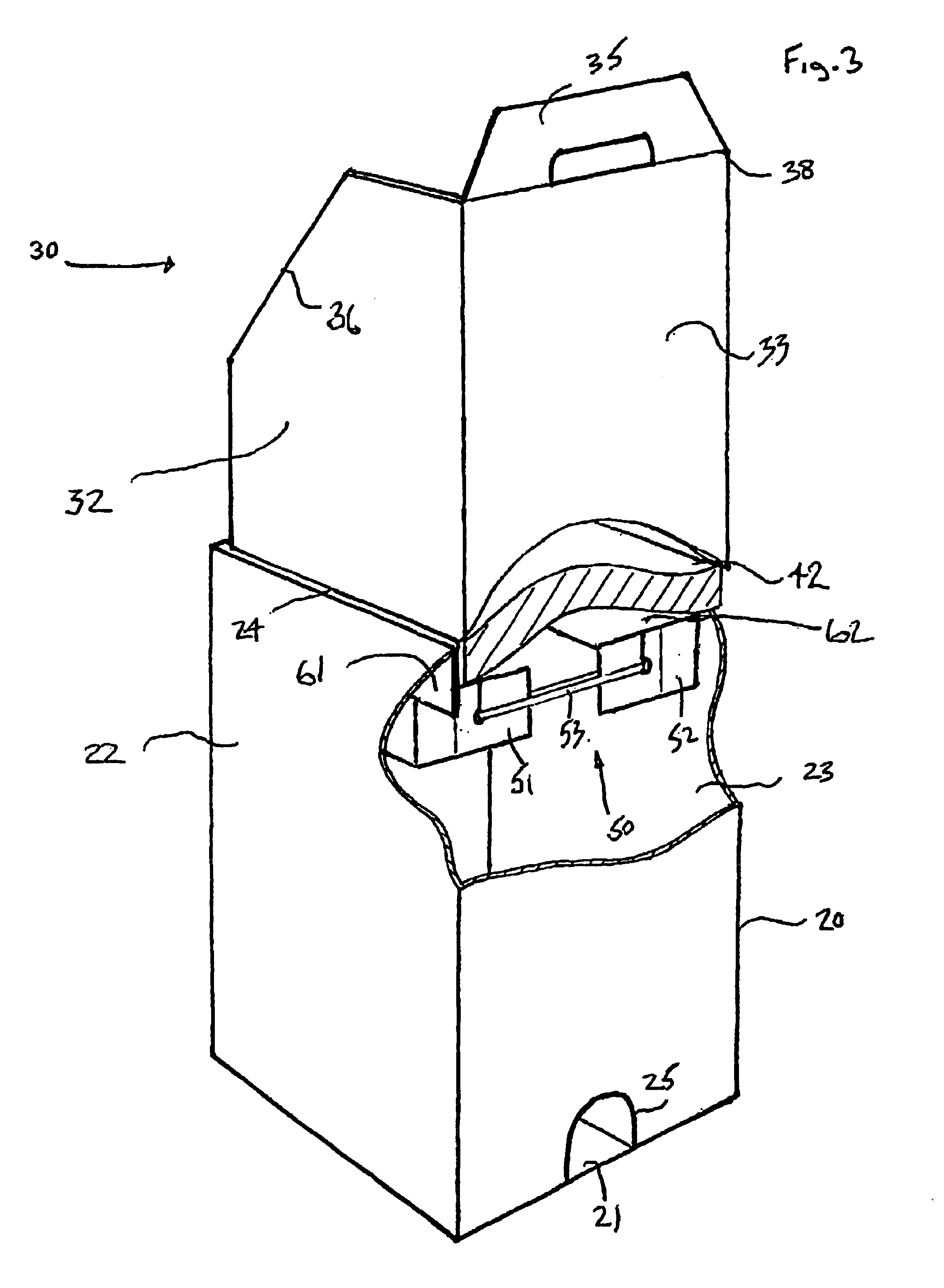
Referring to FIGS. 1 to 4, a transportable merchandise display unit 10 (hereinafter referred to as the display unit) comprises an outer container 20, and an inner display case 30. The outer container 20 is a rectangular section box constructed from a one-piece blank of corrugated cardboard which is folded and glued into place in a known manner. The figures show a box which is of a generally rectangular form. However, other shapes such as square, polygonal or circular section containers are envisaged which may not be constructed from cardboard but from any such other suitably stiff workable material, for example plastics.

The outer container 20 further includes an open top end 22, a floor 21 and a foot-hole 25 in the lower portion of one of the four side walls to provide access to the floor or bottom end of the container 20. The foot-hole is shown positioned in the rear side wall of the display unit 10, and is generally semi-circular shape but it may take any desired form, and be posi...


PUM

PropertyMeasurementUnit
Forceaaaaaaaaaa
Gravityaaaaaaaaaa
Elasticityaaaaaaaaaa

Abstract

A transportable merchandise display unit (10) is provided comprising: an outer container (20) containing an inner display case (30) removable via an opening in the top of said outer container, the outer container including display case support means (50, 50′); the support means arranged to move from a first position to a second position; the first position is resiliently retained by an elastic band until the inner display case is vertically displaced from an initial transit position to a display position, at which instant the support means resiles to the second position to engage and support the inner display case thus preventing the inner display case from returning under the force of gravity to the initial transit position.

Description

FIELD OF THE INVENTIONThis invention relates to a transportable merchandise display unit. In particular, but not exclusively, it relates to stand-alone display structures for use in retail outlets and the like, which are delivered preferably pre-packed with merchandise.BACKGROUND OF THE INVENTIONA common feature of many supermarkets is the promotional display of a new product line. These new lines are often displayed upon plinths located at prominent (and therefore at a premium cost) locations around the shop. Often, as an alternative to the existing on-site plinths, manufacturers ship goods with a ready-to-assemble temporary promotional display structure, adorned with the particular products get-up and / or trade mark (an introductory price discount may also be highlighted). These promotional display structures can take many forms; a common type, particularly with confectionery, is a stiff cardboard “skip” or “bin” into which a supermarket operative (after assembling the “skip” or “b...

Claims


Application Information

Patent Timeline
IPC IPC(8): A47F5/10A47F5/11
CPCA47F5/112Y10S206/805
Inventor MASON, DAVID G.YOUNGS, ROBIN K.
Owner TERRY SMITH GROUP
Learn More