Locking device of a closure with a housing

a technology of locking device and lid, which is applied in the direction of carpet fasteners, mechanical equipment, centrifuges, etc., can solve the problems of affecting the use of the lid, requiring a relative large force expenditure in closing and sealing the lid, etc., and achieves the effect of enhancing the self-locking device action and maximising the operational comfor

Inactive Publication Date: 2006-04-18
EPPENDORF AG
View PDF35 Cites 43 Cited by
  • Summary
  • Abstract
  • Description
  • Claims
  • Application Information

AI Technical Summary

Benefits of technology

[0017]In the first phase, the catch hook is pivoted with the swiveling lever until it impinges on the closing edge of the closure. Then, the second phase begins in which the swiveling lever moves the catch hook downwards and, thus, pulls the closure into the closing position. Such kinematics makes it possible to arrange the swiveling lever, in the aperture position, so as to be completely pivoted into the housing and to form the closing edge on an element which is accessible from the underside of the closure, but does not project therefrom. This means that the housing or the closure do not have projecting elements that are annoying or apt to cause accidents. In addition, the locking device is of a high operational comfort because a substantial expenditure of force in closing and sealing the closure is unnecessary. The kinematics permits to grip the closure with no need for it to be completely closed. At this point, the locking device constitutes some sort of kinematic sensor which pulls the closure onto the seal or into a closing position if the catch hook impinges on the closing edge of the closure. This motion of the closure can also be performed by means of the swiveling lever, with a reduced expenditure of force.
[0020]The drive of the swiveling lever basically may be a manual drive. According to an aspect of the present invention, however, a maximum operational comfort is achieved by using an electric motor as a drive. The fixation of the catch hook in the closing position may be caused or enhanced by a self-locking device or an additional blocking device of a driving transmission. As a blocking device, a driving motor may have a circuit which enables to short-circuit the driving motor in the locking case in order to enhance the self-locking device action. However, there can also be a blocking device mechanically engaging the driving transmission, which can be realized in a relatively easy manner because of the self-locking action thereof.

Problems solved by technology

Generally, manually operable locking devices for lids or other closures require a relative large expenditure of forces in closing and sealing the lid.
Moreover, the known locking devices have hooks or eyelets protruding beyond the housing or the lid, which impede their use or may cause accidents.

Method used


Image

  • Locking device of a closure with a housing
  • Locking device of a closure with a housing
  • Locking device of a closure with a housing

Examples


Embodiment Construction

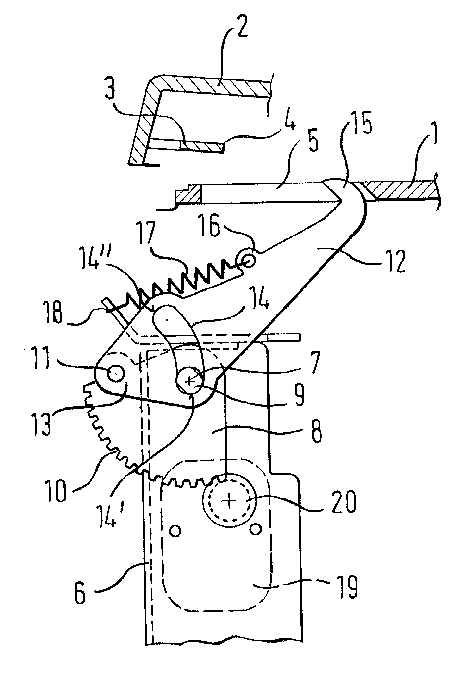
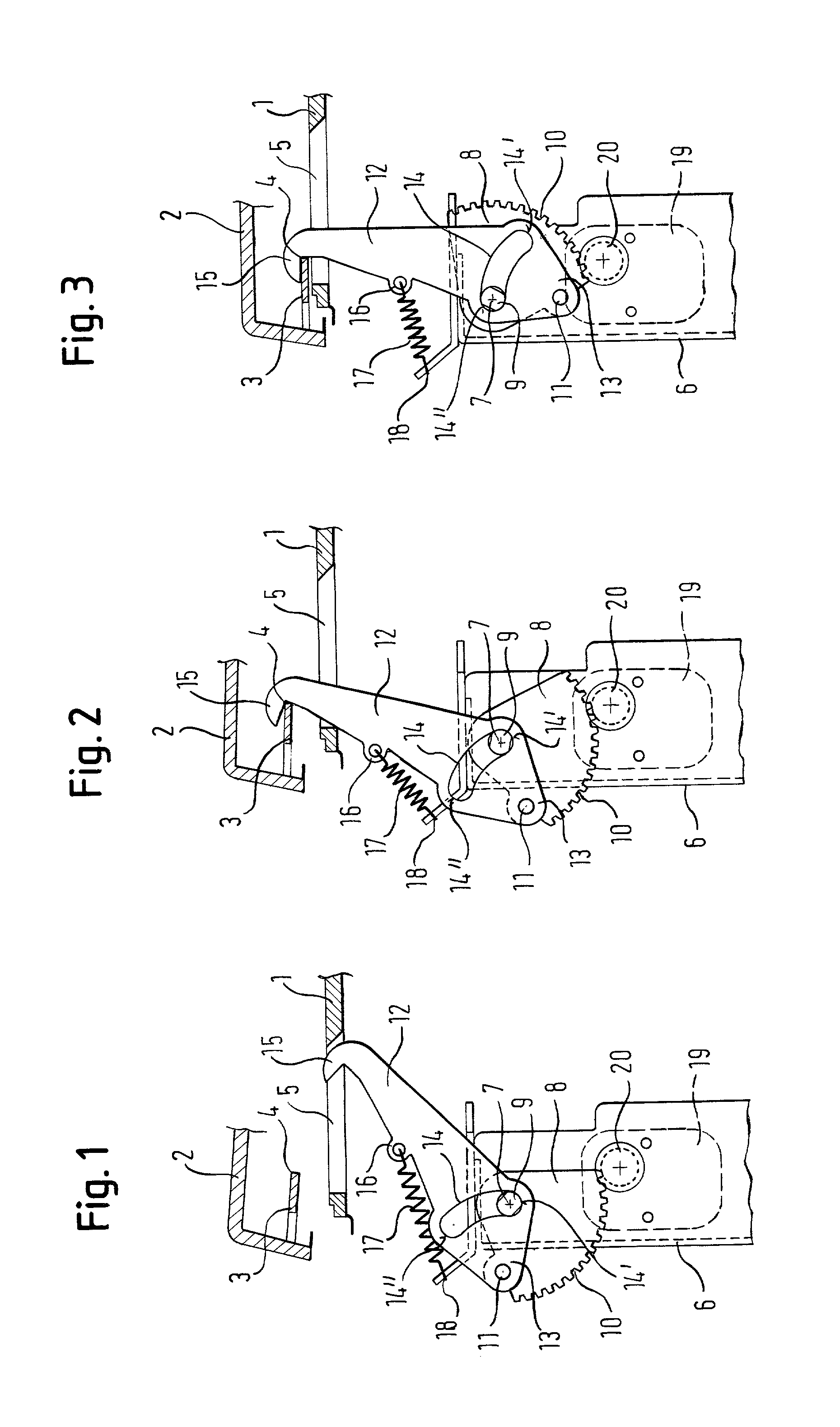
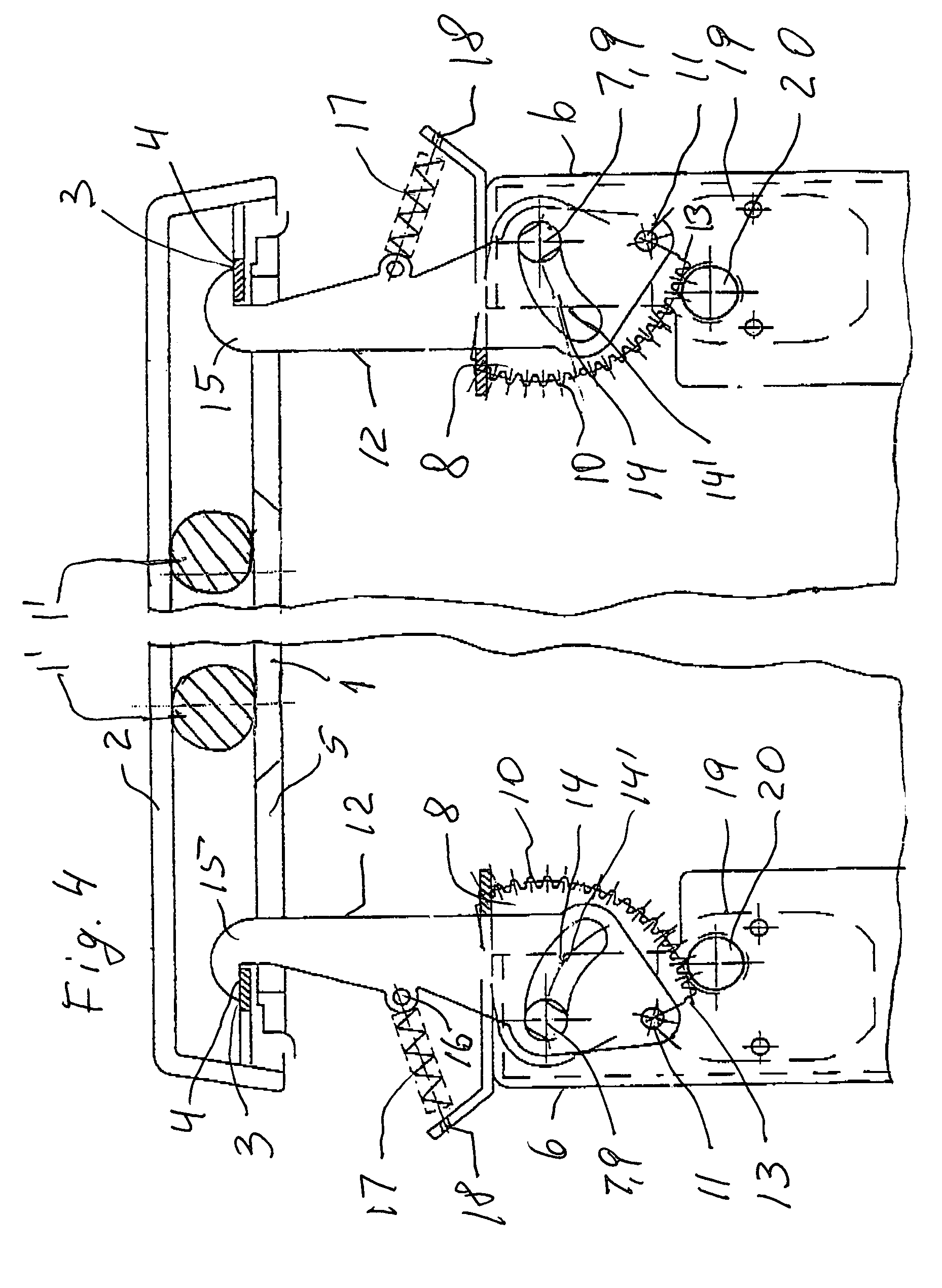
[0034]The locking device is formed on a laboratory centrifuge including a housing 1 and a lid 2 pivotally supported thereon for closing an upper side aperture of the housing 1 through which a centrifuge rotor is accessible. The drawings merely show a portion of housing 1 and lid 2 which is disposed at a spacing from the swivel bearing of the lid 2.

[0035]The lid 2 has a circumferential border which projects downwardly. It is at least from the border inside opposed to the swivel bearing of the lid 2 that an marginal portion 3 projects inwardly the inner border of which defines a closing edge 4.

[0036]In its horizontal upper side, the housing 1 has a slot 5 which extends in a direction transverse to the swivel bearing of the lid 2. The slot 5 starts approximately at the level of the closing edge 4 if the lid 2 is in a closing position and ends at a larger distance from the closing edge 4.

[0037]Within the housing 1, approximately below the slot 5, there are arranged more parts of the loc...


PUM


Abstract

A device for locking a closure (2) with a housing includes at least one swiveling lever (8), a drive (19) for pivoting the at least one swiveling lever 98) about an axis of rotation and having teeth (20) which interact with teeth (10) provided on the marginal area of the swiveling lever extending around the axis of rotation, at least one catch hook (12) supported on the swiveling lever (8) and having a cam segment (14) concentric to the pivot axis (11) of the at least one catch hook and into which a guide element (9) provided on the swiveling lever (8) engages, and a spring (17) for biasing the at least one catch hook in a closing direction.

Description

BACKGROUND OF THE INVENTION[0001]1. Field of the Invention[0002]This invention relates to a device for locking a closure with a housing, particularly of a laboratory centrifuge.[0003]2. Description of the Prior Art[0004]Laboratory centrifuges require to be safely locked when in operation in order to avert dangers of accident caused by a contact with the rotor rotating at a high speed or with content which is centrifuged out. A safe device for locking a closure with a housing is also necessary in many other devices. For example, it can be used with the front flap of a washing machine or the trunk lid of a motor vehicle.[0005]From EP 0 952 385 A2, a safety lock for s has been known, particularly for centrifuges, wherein at least one holder element is passed through the lid underside and is releasably secured within the housing.[0006]The holder element having a hook shape can be pivoted by a strip handle that it partly positively grips around a closing bolt within the housing. When the...

Claims


Application Information

Patent Timeline
Patent Type & Authority Patents(United States)
IPC IPC(8): E05C3/06B04B7/06E05B17/00E05B47/00E05C5/00F16P3/08
CPCB04B7/06E05B47/0012E05C5/00F16P3/08E05B17/0025E05B2047/0021Y10S292/22Y10S292/11E05B2047/0025Y10T292/0928Y10T292/0929Y10T292/0932Y10T292/1054Y10T292/1055Y10T292/1077Y10T292/1082
Inventor LIPPOLDT, ROLANDUHLENDORF, RUDIGERBAUDISCH, HANS-DIETER
Owner EPPENDORF AG
Why Eureka
Try Eureka