Optical recording medium and reproducing device

a technology of optical recording medium and reproducing device, which is applied in the field of optical recording medium, can solve the problems of high coherence of light, drastically reducing the qualities of servo signal and reproduction signal, and achieve good reproduction signal

Active Publication Date: 2009-12-10
PANASONIC CORP
View PDF3 Cites 28 Cited by
  • Summary
  • Abstract
  • Description
  • Claims
  • Application Information

AI Technical Summary

Benefits of technology

[0011]An object of the present invention is to provide an optical recording medium capable of reducing the influence of interference on a servo signal and a reproduction signal in an optical head by preventing reflected lights from other layers from returning to the optical head along the same optical path as reflected light from a readout layer.
[0013]According to the above construction, the return of lights reflected by other layers to an optical head along the same optical path as reflected light from a readout layer during the reproduction can be avoided. Thus, an optical recording medium, from which a good reproduction signal can be obtained, can be provided by suppressing the deterioration of a servo signal and a reproduction signal of a reproducing device due to a variation of interference fringes on a light receiving element.

Problems solved by technology

However, multilayer optical discs have a problem that reflected light from a desired recording layer (hereinafter, “readout layer”) having information reproduced therefrom is mixed with reflected lights from recording layers (hereinafter, “other layers”) other than the readout layer, and some of the reflected lights from the other layers have large influence due to the spacings between the respective recording layers.
Thus, a problem of mixing a signal of the recording layer 103 with a reproduction signal occurs.
Such light has high coherency and forms a light-dark distribution on a light receiving element due to interference.
This becomes a serious problem of drastically reducing the qualities of a servo signal and a reproduction signal.

Method used


Image

  • Optical recording medium and reproducing device
  • Optical recording medium and reproducing device
  • Optical recording medium and reproducing device

Examples


first embodiment

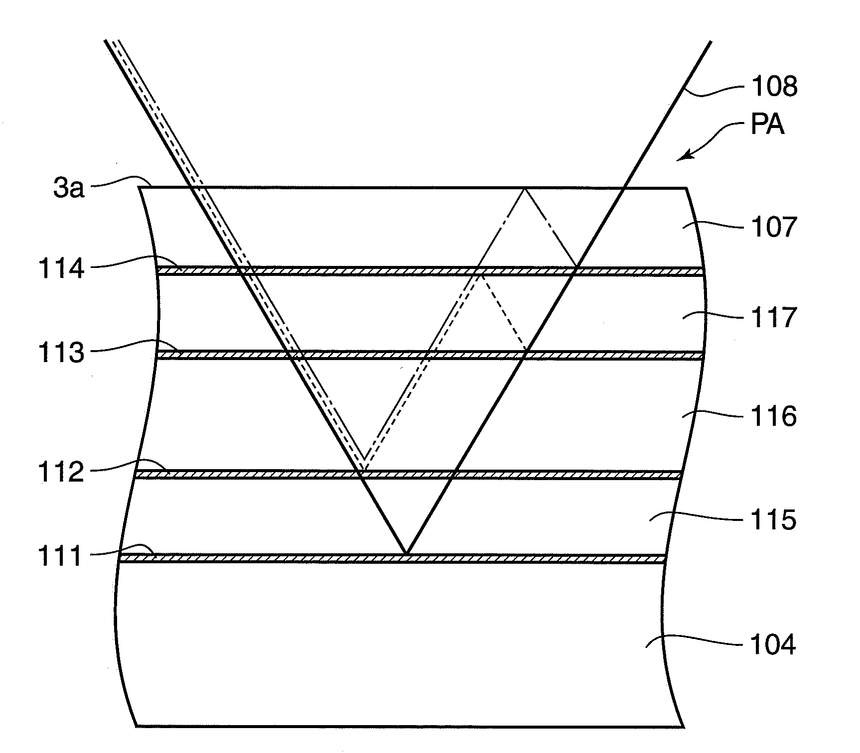
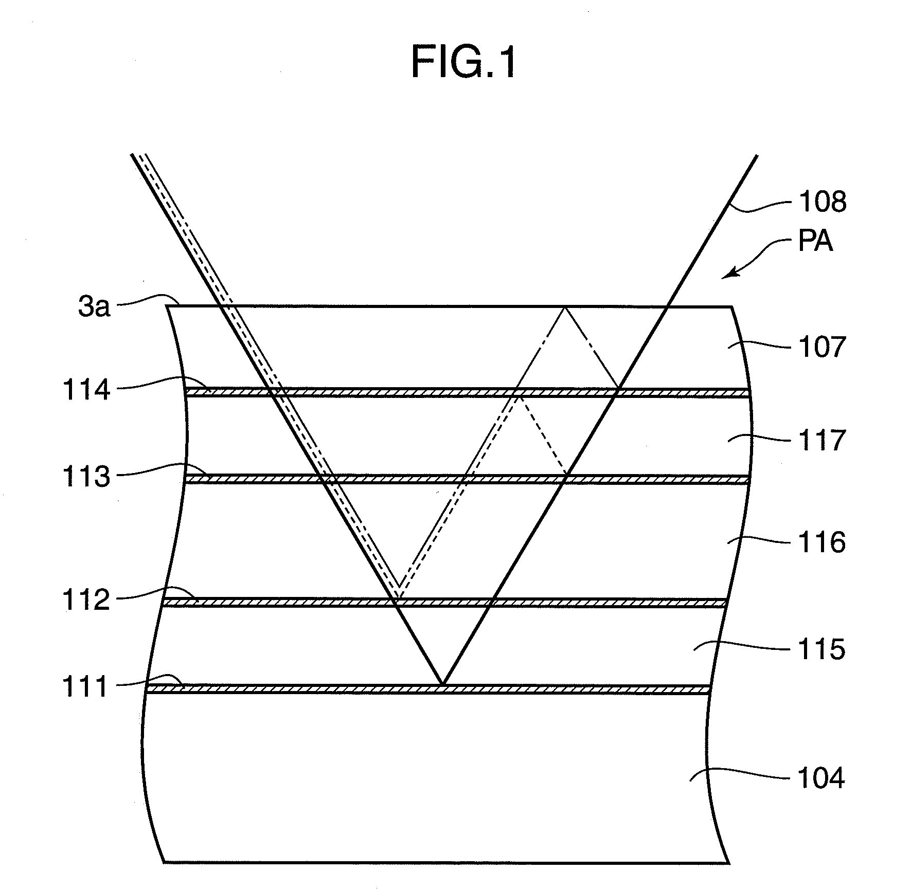
[0055]FIG. 3 is a partial section of an optical disc according to a first embodiment of the present invention. In FIG. 3, identified by 1 is an optical disc with a plurality of recording layers, by 2 a supporting substrate for ensuring a thickness (about 1.2 mm) required for the optical disc 1, by 3 a cover layer having high light transmittance and by 3a a light incident surface of the cover layer 3.

[0056]Identified by 10 to 14 are information recording layers (hereinafter, “recording layers”) for storing data, some or all of the respective recording layers are recording layers exclusively used for reproduction or recordable or rewritable recording layers in which information can be written by a user. Hereinafter, the recording layer 10 is called a layer L0, the recording layer 11 a layer L1, the recording layer 12 a layer L2, the recording layer 13 a layer L3 and the recording layer 14 a layer L4. Identified by 15 to 18 are intermediate layers having high light transmittance and fu...

second embodiment

[0075]FIG. 8 is a partial section of an optical disc according to a second embodiment of the present invention, and FIG. 9 shows spacings between recording layers of the optical disc shown in FIG. 8. This embodiment differs from the first embodiment only in the structure of a disc cross section, and the same constituent elements as those in FIG. 3 are identified by the same reference numerals and not described. The construction of a recording / reproducing device used in this embodiment is the same as that of the first embodiment shown in FIG. 4 and not described in detail.

[0076]In FIG. 8, identified by 20 to 25 are information recording layers for storing data. Hereinafter, the recording layer 20 is called a layer L0, the recording layer 21 a layer L1, the recording layer 22 a layer L2, the recording layer 23 a layer L3, the recording layer 24 a layer L4 and the recording layer 25 a layer L5. Identified by 26 to 30 are intermediate layers having high light transmittance and functioni...

third embodiment

[0092]FIG. 12 is a partial section of an optical disc according to a third embodiment of the present invention, and FIG. 13 shows spacings between recording layers of the optical disc shown in FIG. 12. This embodiment differs from the first embodiment only in the structure of a disc cross section, and the same constituent elements as those in FIG. 3 are identified by the same reference numerals and not described. The construction of a recording / reproducing device used in this embodiment is the same as that of the first embodiment shown in FIG. 4 and not described in detail.

[0093]In FIG. 12, identified by 40 to 46 are information recording layers for storing data. Hereinafter, the recording layer 40 is called a layer L0, the recording layer 41 a layer L1, the recording layer 42 a layer L2, the recording layer 43 a layer L3, the recording layer 44 a layer L4, the recording layer 45 a layer L5 and the recording layer 46 a layer L6. Identified by 47 to 52 are intermediate layers having ...


PUM

PropertyMeasurementUnit
thicknessaaaaaaaaaa
light wavelengthaaaaaaaaaa

Abstract

An optical recording medium is provided with a plurality of recording layers, wherein the recording layers are formed such that all the spacings between two recording layers in all the combinations selected from the plurality of recording layers do not coincide with each other. Accordingly, the return of lights reflected by other layers to an optical head along the same optical path as reflected light from a readout layer during the reproduction can be avoided. Therefore, an optical recording medium, from which a good reproduction signal can be obtained, can be provided by suppressing the deterioration of a servo signal and a reproduction signal of a reproducing device due to a variation of interference fringes on a light receiving element.

Description

FIELD OF TECHNOLOGY[0001]The present invention relates to an optical recording medium with a multitude of information recording layers and particularly to an interlayer spacing structure of a multilayer optical disc provided with five or more information recording layers or a cover layer and four or more information recording layers.DESCRIPTION OF THE BACKGROUND ART[0002]In recent years, the use of optical discs in audio field, video field, computer field and many other fields has been promoted since a large quantity of information signals can be recorded at a high density. Recording capacity required for such optical discs increases year after year and various methods have been and are being proposed to accomplish this. A method for forming an information recording layer (hereinafter, “recording layer”) of an optical disc into a double layer structure has been proposed as one of them and already put to practical use.[0003]Such optical discs are structured to laminate recording laye...

Claims


Application Information

Patent Timeline
Patent Type & Authority Applications(United States)
IPC IPC(8): G11B7/26G11B7/24G11B7/24038
CPCG11B7/24038
Inventor NAGATA, TAKAYUKIANZAI, JOJIAIKOH, HIDEKI
Owner PANASONIC CORP
Why Eureka
Try Eureka