Cable detection apparatus and method
a detection apparatus and cable technology, applied in the direction of nuclear radiation detection, reradiation, transmission, etc., can solve the problems of reducing the accuracy of detection and location, affecting the accuracy of detection, and high noise levels, so as to reduce interference, reduce noise, and reduce noise
- Summary
- Abstract
- Description
- Claims
- Application Information
AI Technical Summary
Benefits of technology
Problems solved by technology
Method used
Image
Examples
first embodiment
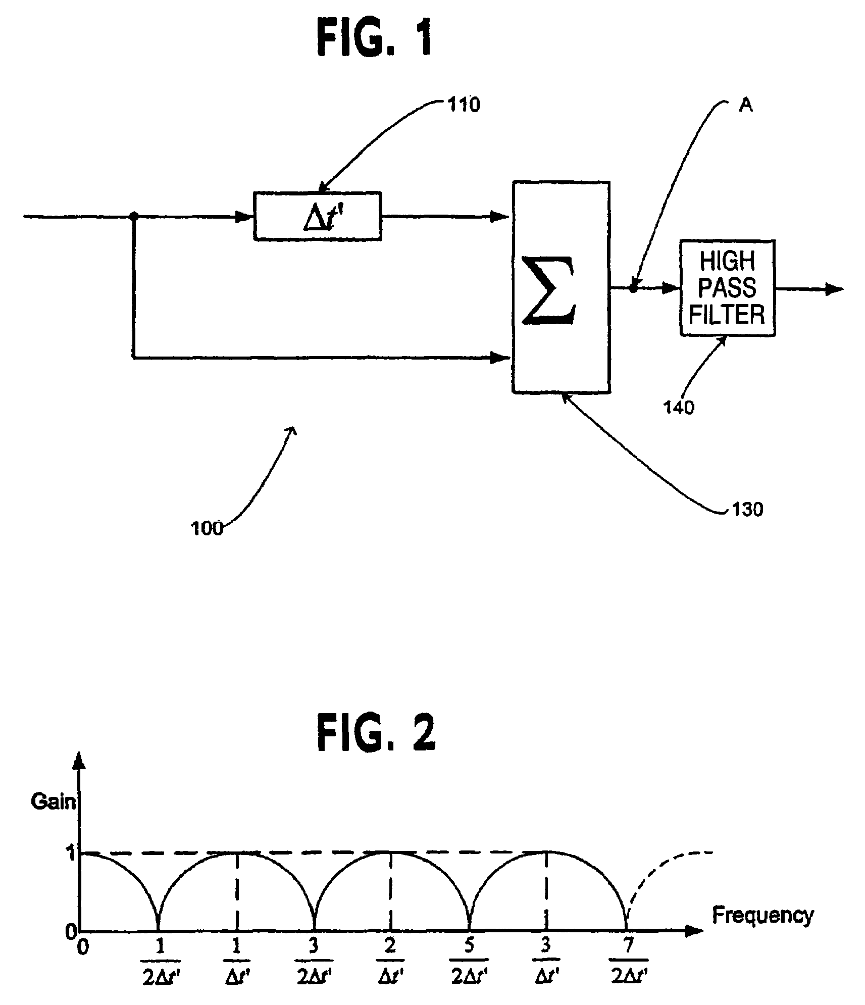
[0027]FIG. 1 shows a type 1 comb filter 100 for use in a cable detection apparatus according to the invention. The filter comprises a time delay unit 110, and an adder 130. In the present embodiment, a signal input into the filter 100 comprises multiple frequency components. The input signal is split; half is delayed by a time internal Δt′ by the time delay unit 110 before being output to the adder 130, while the other half is input directly into the adder 130. The adder 130 outputs the sum of the two inputs and therefore has a peak in transmittance when the time delay is an exact multiple of the cycle length or period, of the input signal.
[0028]An optional high pass filter 140 is also included. The high pass filter removes D.C. signals. In an embodiment, the high pass filter also removes the fundamental frequency of the signal passed through the filter 100. The filter 140 may alternatively be omitted.
[0029]A typical frequency response of the type 1 filter at point A is given in FIG...
second embodiment
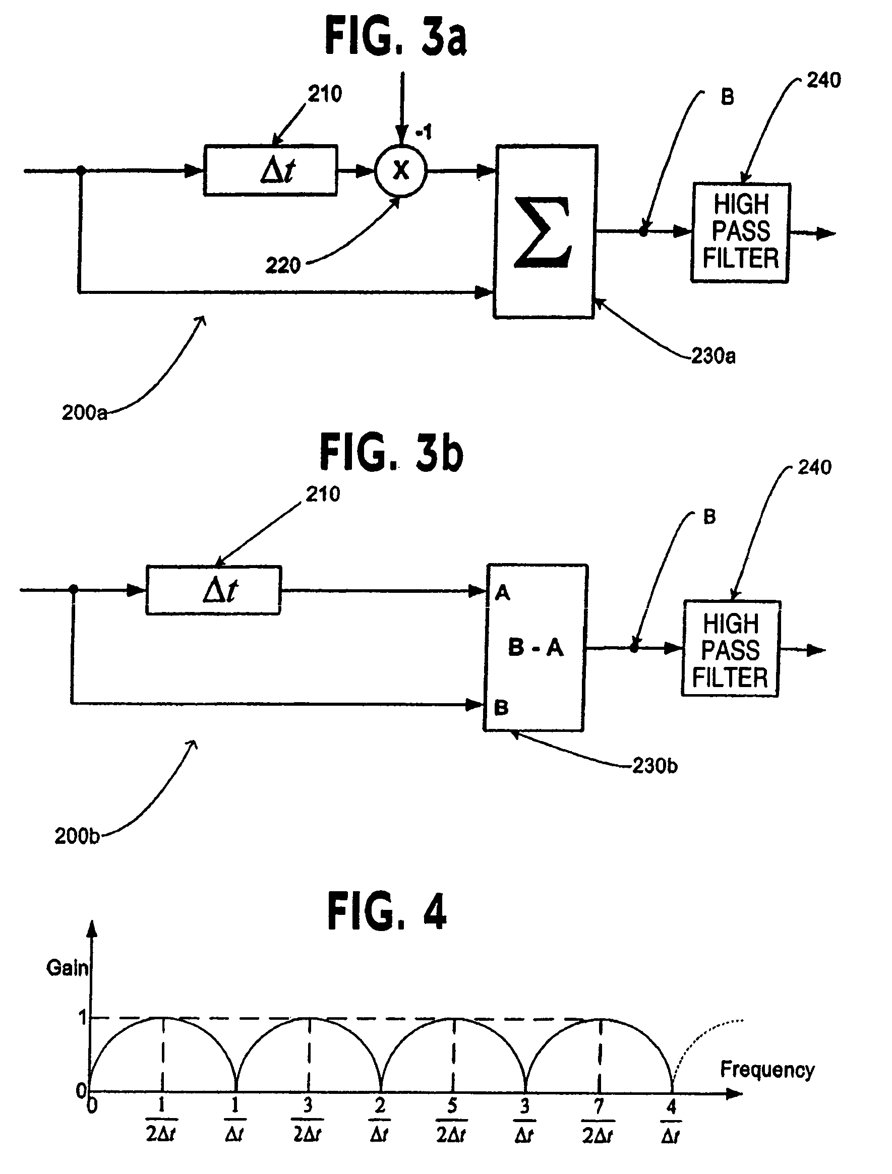
[0030]FIG. 3a shows a schematic of a type 2 comb filter 200a, used in a device for detection of cables according to the invention, which can be used either on its own or with one or more type 1 comb filters according to embodiments of the present invention. The filter 200a comprises a time delay unit 210 to receive an input signal, an inverter 220 connected to the time delay unit 210, and an adder 230a connected to the inverter 220 and also to receive the input signal.
[0031]The type 2 filter 200a operates by firstly receiving and splitting an input signal. The type 2 filter 200a differs from the type 1 filter 100 in that it has an inverter 220.
[0032]In the present embodiment, the signal comprises multiple frequency components. The input signal is split to the time delay unit 210, as well as directly to the adder 230a. The inverter 220 receives the output from the time delay unit 210 and inverts the signal received by it (multiplies it by −1) and outputs the inverted signal to the ad...
third embodiment
[0040]FIG. 5 shows a filter system according to the invention. The filter system comprises a first and second type 1 comb filter 510 and 520, of the type discussed above, and a first and second type 2 comb filter 530 and 540, as discussed above, cascaded, i.e. connected in series. In embodiments of the invention, a single type 1 filter 100 can be used with a single type 2 filter 200a, 200b. Use of the two filters together will result in reduction of even harmonics and increased removal of non-harmonic noise, compared with use of a single type 1 filter. Alternatively, multiple type 1 and / or type 2 filters can be used in combination, which will lead to an increased removal of non-harmonic and even harmonic noise.
[0041]As discussed above, the type 1 filters have a time delay (Δt′) of 20 ms. The type 2 filters have a delay (Δt) of 10 ms. The filters are thus tuned have peak transmittance at a fundamental frequency of 50 Hz. The type 1 filters reduce non-harmonic noise, and the type 2 fi...
PUM
 Abstract
Description
Claims
Application Information
 - R&D
- Intellectual Property
- Life Sciences
- Materials
- Tech Scout
- Unparalleled Data Quality
- Higher Quality Content
- 60% Fewer Hallucinations
Browse by: Latest US Patents, China's latest patents, Technical Efficacy Thesaurus, Application Domain, Technology Topic, Popular Technical Reports.
© 2025 PatSnap. All rights reserved.Legal|Privacy policy|Modern Slavery Act Transparency Statement|Sitemap|About US| Contact US: help@patsnap.com


