Cable detection apparatus and method

Inactive Publication Date: 2005-12-20
RADIODETECTION
View PDF15 Cites 46 Cited by
  • Summary
  • Abstract
  • Description
  • Claims
  • Application Information

AI Technical Summary

Benefits of technology

[0006]According to a first aspect of the invention, there is provided a cable detection or location device comprising a filter that can reduce the effects of interference on an electromagnetic field emitted from a buried, underground or otherwise inaccessible object. The filter filters the signal received at the device, and suppresses certain frequency components. Non-harmonic frequ

Problems solved by technology

However, use of electromagnetic fields in detection can be compromised by high levels of noise being detected along with the signa

Method used


Image

  • Cable detection apparatus and method
  • Cable detection apparatus and method
  • Cable detection apparatus and method

Examples


first embodiment

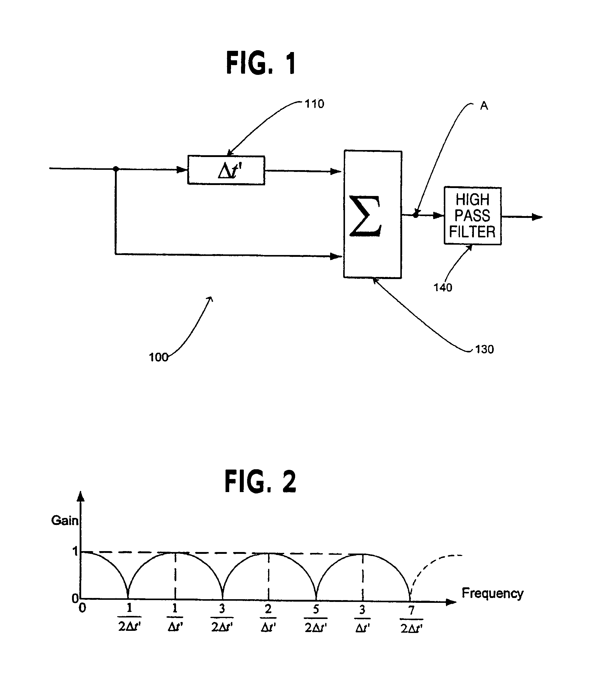
[0026]FIG. 1 shows a type 1 comb filter 100 for use in a cable detection apparatus according to the invention. The filter comprises a time delay unit 110, and an adder 130. In the present embodiment, a signal input into the filter 100 comprises multiple frequency components. The input signal is split; half is delayed by a time internal Δt′ by the time delay unit 110 before being output to the adder 130, while the other half is input directly into the adder 130. The adder 130 outputs the sum of the two inputs and therefore has a peak in transmittance when the time delay is an exact multiple of the cycle length or period, of the input signal.

[0027]An optional high pass filter 140 is also included. The high pass filter removes D.C. signals. In an embodiment, the high pass filter also removes the fundamental frequency of the signal passed through the filter 100. The filter 140 may alternatively be omitted.

[0028]A typical frequency response of the type 1 filter at point A is given in FIG...

second embodiment

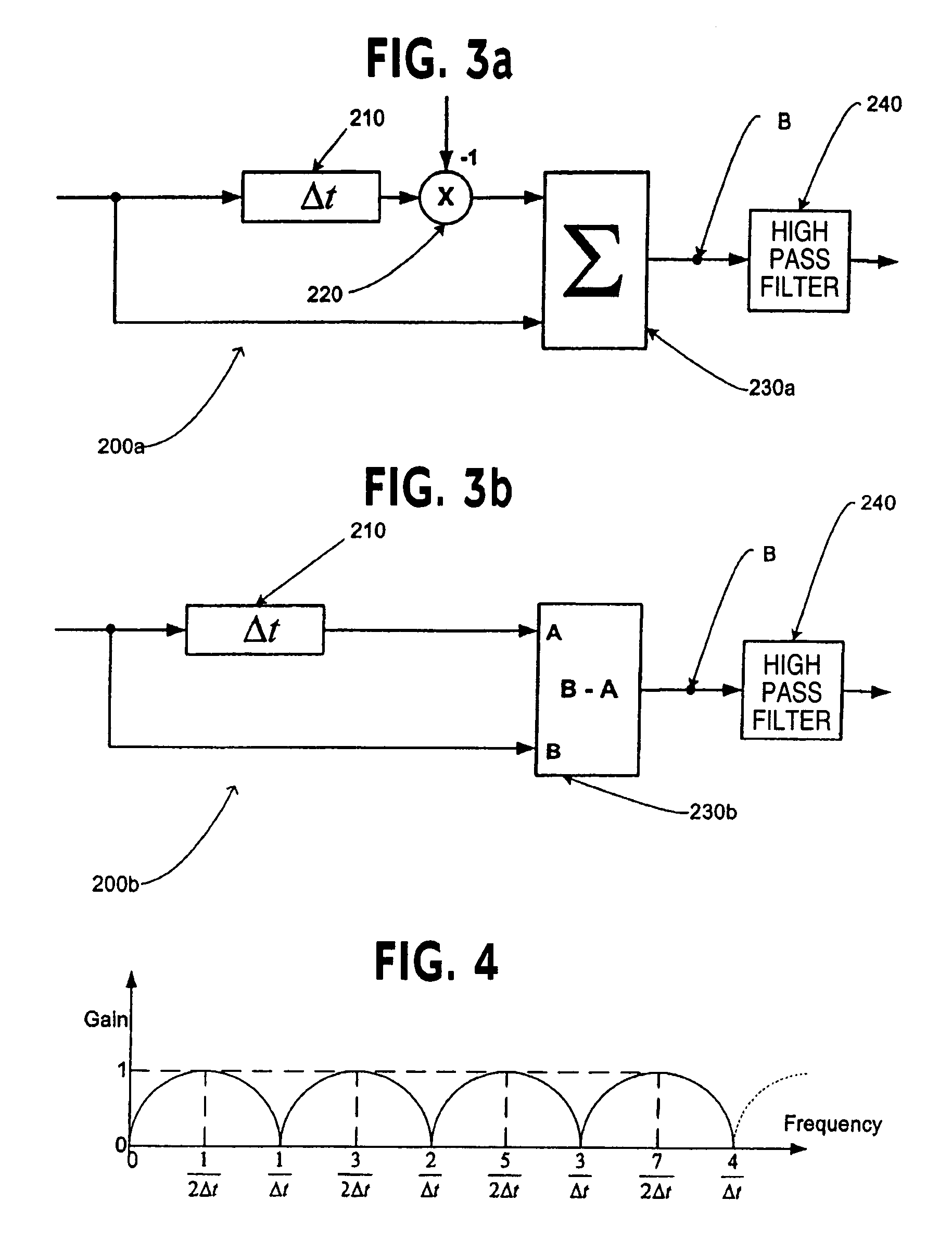
[0029]FIG. 3a shows a schematic of a type 2 comb filter 200a, used in a device for detection of cables according to the invention, which can be used either on its own or with one or more type 1 comb filters according to embodiments of the present invention. The filter 200a comprises a time delay unit 210 to receive an input signal, an inverter 220 connected to the time delay unit 210, and an adder 230a connected to the inverter 220 and also to receive the input signal.

[0030]The type 2 filter 200a operates by firstly receiving and splitting an input signal. The type 2 filter 200a differs from the type 1 filter 100 in that it has an inverter 220.

[0031]In the present embodiment, the signal comprises multiple frequency components. The input signal is split to the time delay unit 210, as well as directly to the adder 230a. The inverter 220 receives the output from the time delay unit 210 and inverts the signal received by it (multiplies it by −1) and outputs the inverted signal to the ad...

third embodiment

[0039]FIG. 5 shows a filter system according to the invention. The filter system comprises a first and second type 1 comb filter 510 and 520, of the type discussed above, and a first and second type 2 comb filter 530 and 540, as discussed above, cascaded, i.e. connected in series. In embodiments of the invention, a single type 1 filter 100 can be used with a single type 2 filter 200a, 200b. Use of the two filters together will result in reduction of even harmonics and increased removal of non-harmonic noise, compared with use of a single type 1 filter. Alternatively, multiple type 1 and / or type 2 filters can be used in combination, which will lead to an increased removal of non-harmonic and even harmonic noise.

[0040]As discussed above, the type 1 filters have a time delay (Δt′) of 20 ms. The type 2 filters have a delay (Δt) of 10 ms. The filters are thus tuned have peak transmittance at a fundamental frequency of 50 Hz . The type 1 filters reduce non-harmonic noise, and the type 2 f...


PUM


Abstract

A cable detection apparatus is disclosed having a filter, the filter transmitting components of a signal detected substantially at certain harmonics of a first frequency. The filter may also attenuate the signal at certain even harmonics thereof. A method of detecting and/or locating cables in the same manner is also disclosed.

Description

FIELD OF THE INVENTION[0001]The present invention relates to reduction of noise in cable detection systems.BACKGROUND OF THE INVENTION[0002]Before commencing excavation or other work where power or other cables may be buried, it is important to determine the location of the cables to ensure that they are not damaged during the work. It is also useful to be able to track the path of buried or otherwise inaccessible power cables. It is known to use detectors that detect the electromagnetic field emitted by power cables carrying alternating currents.[0003]The electromagnetic field emitted by a power cable has a fundamental frequency equal to the frequency of the alternating current carried by the cable. However, harmonic frequencies (multiples in frequency) of this fundamental frequency are generally also emitted. The harmonics are emitted at two, three, four, etc times the fundamental frequency. The second, fourth, sixth etc harmonics are called even harmonics, and the third, fifth, s...

Claims


Application Information

Patent Timeline
IPC IPC(8): G01V3/08G01V15/00
CPCG01V3/081G01V15/00
Inventor PEARSON, RICHARD D.KING, JAMES IAN
Owner RADIODETECTION
Why Eureka
Try Eureka