Laser welding suction nozzle and laser welding torch

A technology of laser welding and welding area, applied in laser welding equipment, welding equipment, welding equipment and other directions, can solve the problem of large overall size of the nozzle, and achieve the effect of avoiding difficult processing, reducing energy dissipation, and reducing the influence of interference

Active Publication Date: 2022-03-08
SUZHOU RS TECH
View PDF0 Cites 0 Cited by
  • Summary
  • Abstract
  • Description
  • Claims
  • Application Information

AI Technical Summary

Problems solved by technology

[0003] In order to ensure stable suction and stable positioning of the workpiece during the welding process, the existing laser welding suction nozzle involves many auxiliary parts, resulting in a large overall volume of the suction nozzle. The optical path causes greater interference, especially when welding delicate parts, this problem is particularly prominent

Method used


Image

  • Laser welding suction nozzle and laser welding torch
  • Laser welding suction nozzle and laser welding torch
  • Laser welding suction nozzle and laser welding torch

Examples


Embodiment 1

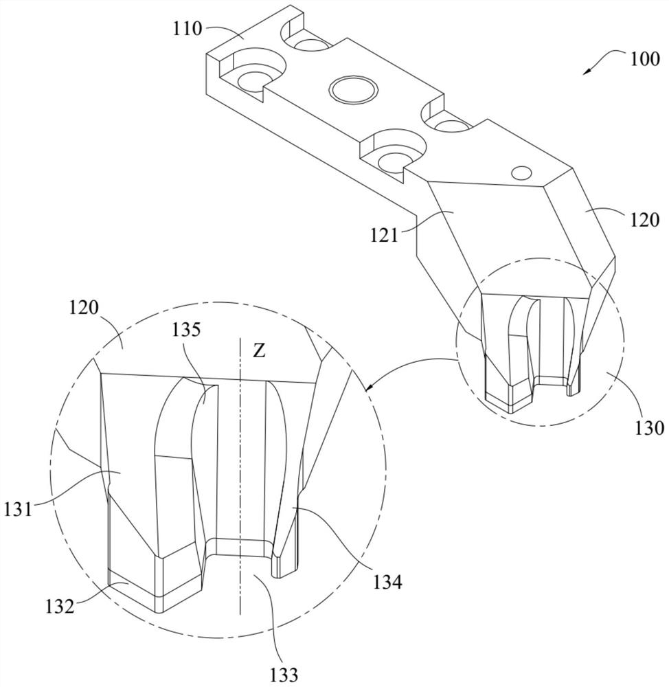
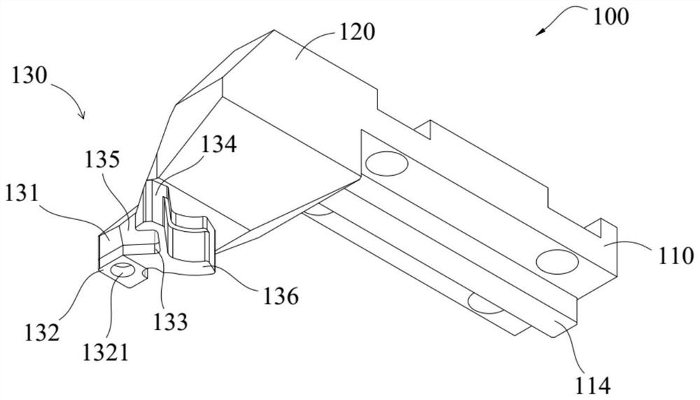
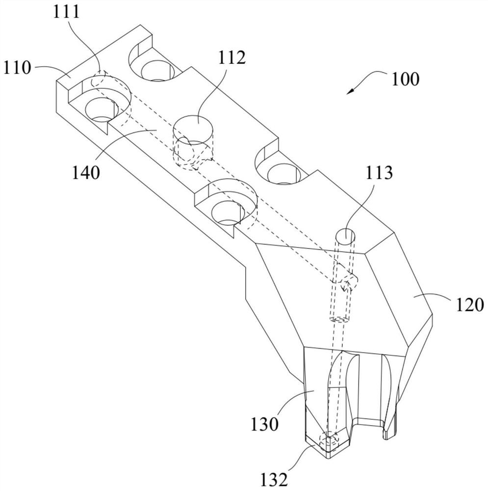
[0057] According to an embodiment of the present invention, a combination of Figure 1 ~ Figure 3 From the illustration, it can be seen that the laser welding nozzle 100 includes:

[0058] Mounting section 110;

[0059] a suspension section 120, which is integrally joined to the installation section 110 at one end of the installation section 110 and extends downward from the installation section 110; and

[0060] an extension section mounted to the bottom of the overhanging section 120;

[0061] Wherein, at least part of the outer periphery of the extension section protrudes from the outside of the overhanging section 120 to form a convex portion 130, and a light-transmitting hole 133 is opened through the upper and lower surfaces of the convex portion 130, and the light-transmitting The hole 133 is open at its outer side to separate the convex portion 130 into a suction block 131 and a pressing block 134 . refer to Figure 22 , during welding, the laser welding suction no...

Embodiment 2

[0074] According to an embodiment of the present invention, a combination of Figure 8 ~ Figure 11 From the illustration, it can be seen that the laser welding nozzle 200 includes:

[0075] Mounting section 210;

[0076]a suspension section 220, which is integrally joined to the installation section 210 at one end of the installation section 210 and extends downward from the installation section 210; and

[0077] an extension section mounted to the bottom of the overhanging section 220;

[0078] Wherein, at least part of the outer periphery of the extension section protrudes from the outside of the overhanging section 220 to form a convex portion 230, and a light-transmitting hole 233 is opened through the upper and lower surfaces of the convex portion 230, and the light-transmitting The hole 233 is opened on its outer side to separate the protruding part 230 into a suction block 231 and a pressing block 234 . During welding, the laser welding suction nozzle 200 sucks the w...

Embodiment 3

[0091] According to an embodiment of the present invention, a combination of Figure 15 ~ Figure 17 As shown, it can be seen that the laser welding nozzle 300 includes:

[0092] Mounting section 310;

[0093] a suspension section 320, which is integrally joined to the installation section 310 at one end of the installation section 310 and extends downward from the installation section 310; and

[0094] an extension section mounted to the bottom of the overhang section 320;

[0095] Wherein, at least part of the outer periphery of the extension section protrudes from the outside of the overhanging section 320 to form a convex portion 330, and a light-transmitting hole 333 is opened through the upper and lower surfaces of the convex portion 330, and the light-transmitting The hole 333 is open at its outer side to separate the protruding portion 330 into a suction block 331 and a pressing block 334 . During welding, the laser welding nozzle 300 sucks the workpiece through the ...


PUM


Abstract

The invention discloses a laser welding suction nozzle and a laser welding torch. The laser welding suction nozzle comprises: an installation section; extending downward; and an extension section, which is installed to the bottom of the overhanging section; wherein, the outer periphery of the extension section at least partially protrudes from the outside of the overhanging section to form an outer protrusion, and the outer protrusion has a The light-transmitting hole runs through the upper and lower surfaces thereof, and the light-transmitting hole is opened on the outer side so as to separate the convex part into a suction block and a pressing block. According to the present invention, the light-transmitting hole is set on the suction nozzle without reserving an additional laser avoidance station on the side of the suction nozzle, so that the lateral installation space of the suction nozzle is kept small enough, and the laser beam can pass through the light-transmitting hole Injecting from directly above the workpiece reduces the energy dissipation of the laser beam due to the intentional extension of the laser optical path, and improves the welding efficiency and welding quality.

Description

technical field [0001] The invention relates to the field of laser welding, in particular to a laser welding suction nozzle and a laser welding torch. Background technique [0002] In the field of laser welding, it is well known to adopt welding suction nozzles of different structural forms to realize suction and positioning of workpieces after suction. In the process of researching and realizing the stable suction and positioning of the workpiece to be welded, the inventor found that the laser welding nozzle in the prior art has at least the following problems: [0003] In order to ensure stable suction and stable positioning of the workpiece during the welding process, the existing laser welding suction nozzle involves many auxiliary parts, resulting in a large overall volume of the suction nozzle. The optical path causes greater interference, especially when welding delicate parts, this problem is particularly prominent. [0004] In view of this, it is necessary to deve...

Claims


Application Information

Patent Timeline
Patent Type & Authority Patents(China)
IPC IPC(8): H01L21/60
CPCB23K26/21B23K26/702B23K37/04
Inventor 缪磊袁文卿肖夕全刘端琰
Owner SUZHOU RS TECH
Why Eureka
Try Eureka