

Suction mechanism for laser welding
A suction mechanism and laser welding technology, applied in laser welding equipment, welding equipment, metal processing equipment, etc., can solve the problems of large and redundant suction mechanism, complex suction mechanism structure, and heavy suction mechanism, so as to improve the success of suction. high efficiency, compact structure and small installation space
- Summary
- Abstract
- Description
- Claims
- Application Information
AI Technical Summary
Problems solved by technology
Method used
Image

Examples
Embodiment 1
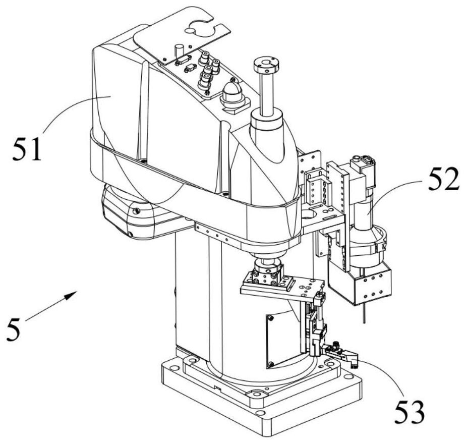
[0068] combine Figure 1 to Figure 7 From the illustration, it can be seen that the suction mechanism 5 for laser welding includes:
[0069] suction mount 53; and
[0070] The suction nozzle 100 installed on the suction mounting seat 53;
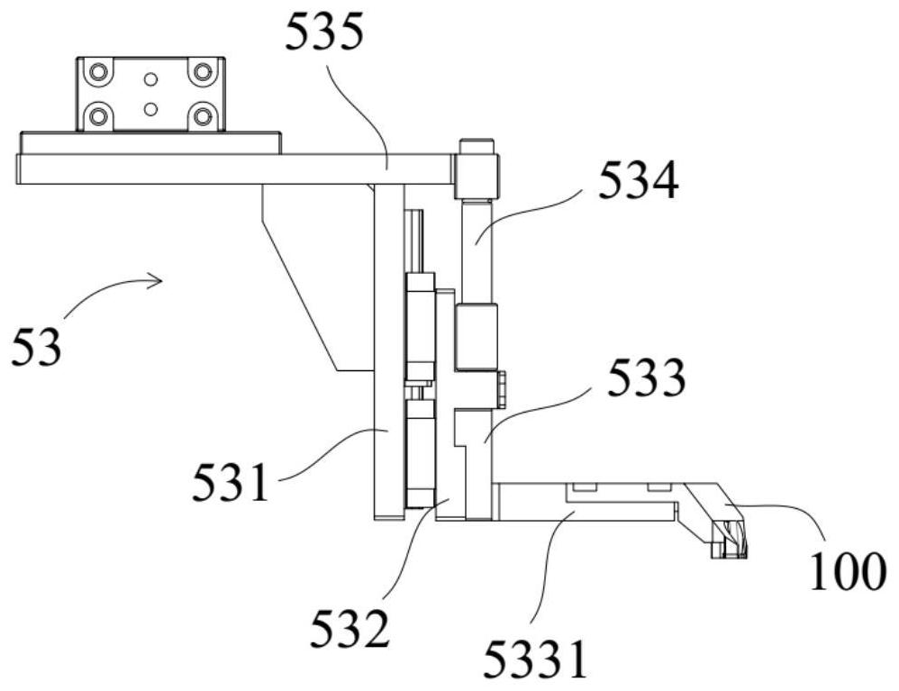
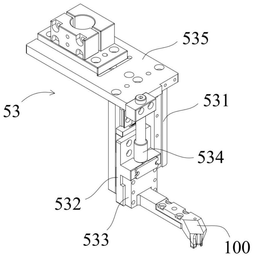
[0071] Wherein, the suction mount 53 includes:
[0072] An installation riser 531 extending vertically;
[0073] A sliding mounting plate 532 slidingly connected to the side of the mounting vertical plate 531, the sliding mounting plate 532 can slide back and forth in the vertical direction relative to the mounting vertical plate 531 to switch between the natural state and the buffer state; as well as
[0074] The suction nozzle installation seat 533 fixedly installed with the sliding installation plate 532, the side of the suction nozzle installation seat 533 is fixedly connected with the suction nozzle installation cantilever 5331, and the suction nozzle installation cantilever 5331 is lifted from the suction nozzle installation seat 5...
Embodiment 2
[0094] Another variant of the above-mentioned suction mechanism for laser welding will be found in Figure 15 ~ Figure 21 It is shown in , wherein the components corresponding to the first embodiment are referred to by the same reference numerals, and in order to save space, only different implementation forms of the suction nozzle are described.
[0095] According to an embodiment of the present invention, a combination of Figure 15 ~ Figure 18 As shown, it can be seen that the suction nozzle 200 includes:
[0096] Mounting section 210;
[0097] a suspension section 220, which is integrally joined to the installation section 210 at one end of the installation section 210 and extends downward from the installation section 210; and
[0098] an extension section mounted to the bottom of the overhanging section 220;
[0099] Wherein, at least part of the outer periphery of the extension section protrudes from the outside of the overhanging section 220 to form a convex portion...
Embodiment 3
[0111] Another variant of the above-mentioned suction mechanism for laser welding will be found in Figure 22 to Figure 28 It is shown in , wherein the components corresponding to the first embodiment are referred to by the same reference numerals, and in order to save space, only different implementation forms of the suction nozzle are described.
[0112] According to an embodiment of the present invention, a combination of Figure 22 ~ Figure 24 As shown, it can be seen that the suction nozzle 300 includes:
[0113] Mounting section 310;
[0114] a suspension section 320, which is integrally joined to the installation section 310 at one end of the installation section 310 and extends downward from the installation section 310; and
[0115] an extension section mounted to the bottom of the overhang section 320;
[0116] Wherein, at least part of the outer periphery of the extension section protrudes from the outside of the overhanging section 320 to form a convex portion 3...
PUM
 Abstract
Description
Claims
Application Information