Portable conveyor system with drive-over unloading ramp and a longitudinal conveyor feeding a bucket elevator

a conveyor system and drive-over unloading technology, which is applied in the direction of conveyors, conveyor parts, transportation and packaging, etc., can solve the problems of increasing the complexity and time involved in setting up the mobile plant for use, the difficulty of accurately positioning the large transport vehicle and the transfer auger inlet, and the physical challenge and/or time-consuming

Active Publication Date: 2017-05-30
NORSTAR IND
View PDF14 Cites 31 Cited by
  • Summary
  • Abstract
  • Description
  • Claims
  • Application Information

AI Technical Summary

Benefits of technology

[0040]Preferably the control system is configured to prevent deployment of the feeder conveyor by the at least one feeder conveyor actuator in the absence of a detected level condition of the transportable frame by the at least one tilt sensor.
[0043]The control system may be configured to prevent deployment of the feeder conveyor from the stowed position to the use position prior to deployment of the main conveyor from the storage position to the operational position.
[0044]The control system may be configured to prevent return of the main conveyor from the raised position to the storage position prior to return of the feeder conveyor to the stowed position from the use position.
[0084]There may be provided ramp position sensors for detecting a positional status of the drive-over ramps, and the control system is configured to prevent return of the feeder conveyor to the respective storage position thereof until the drive-over ramps are retracted out of the deployed positions.

Problems solved by technology

A known challenge in various industries requiring transport of particulate material is to find cost-effective and time and space efficient solutions for conveying particulate material to elevated locations, for example to an inlet opening at the top of an upright storage bin in which the particulate material is to be stored for subsequent use.
However, one potential drawback is the notable cost of incorporating a dedicated conveyor at every proppant storage tank.
However, accurate relative positioning between a large transport vehicle and the transfer auger inlet can be physically challenging and / or time consuming, especially if available space around the bin is limited by the presence of trees, additional bins, or other structures.
This increases the complexity and time involved to setup the mobile plant for use.
Chinese Utility Model 2478984 teaches a wheel conveyor apparatus for filling of grain bins, but lacks an onboard solution for feeding of the conveyor from a hopper bottom vehicle in a drive-over manner.
PCT Application Publication 2011 / 0707975 teaches a mobile asphalt mixing plant including multiple on-board conveyors, but again lacks a built in drive-over unloading Solution for trucked-in source materials.
European Patent 0230883 teaches a mobile bucket elevator for handling of bulk materials, but also lacks a drive-over unloading solution.

Method used


Image

  • Portable conveyor system with drive-over unloading ramp and a longitudinal conveyor feeding a bucket elevator
  • Portable conveyor system with drive-over unloading ramp and a longitudinal conveyor feeding a bucket elevator
  • Portable conveyor system with drive-over unloading ramp and a longitudinal conveyor feeding a bucket elevator

Examples


first embodiment

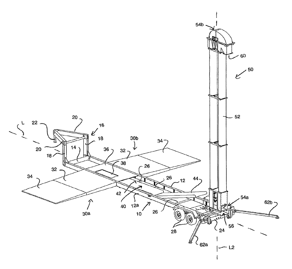
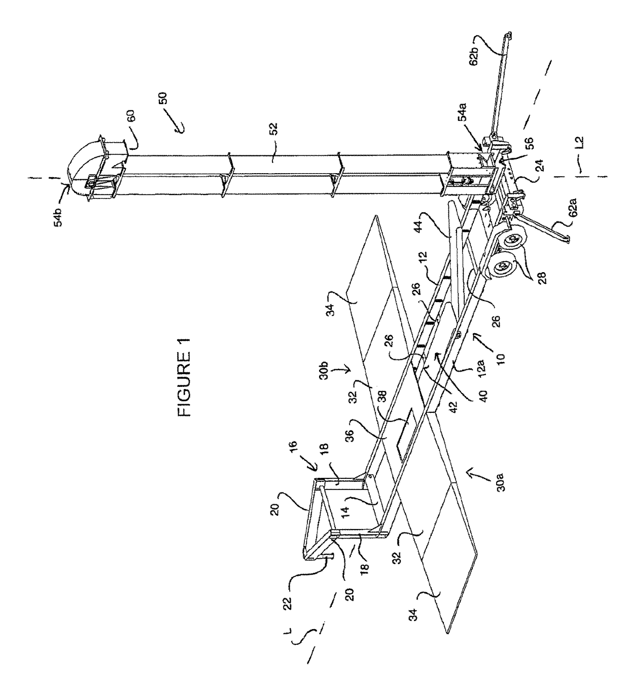
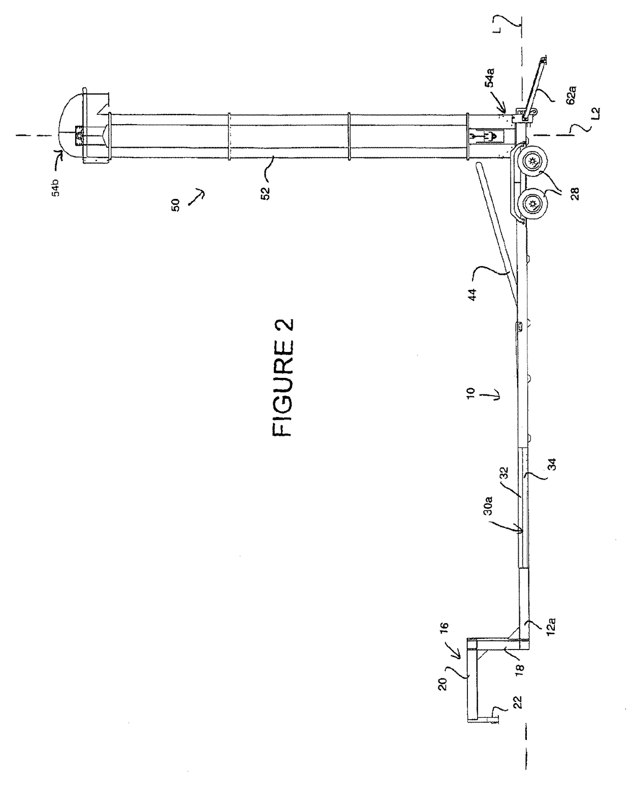
[0140]Near the first end of the trailer frame 10, a first ramp assembly 30a is connected to the longitudinal beam 12a on one side of the trailer frame, and a second ramp assembly 30b is connected to the other longitudinal beam 12b on the other side of the trailer frame 10. In the illustrated first embodiment, the two ramp assemblies are identical to one another, and accordingly further description is made with only reference to one of the two ramp assemblies. A first ramp section 32 features a hinged connection to the respective longitudinal beam 12a of the trailer frame 10 in order to provide this first ramp section 32 with a pivot axis that is parallel to the trailer's longitudinal axis L. The first ramp section can move about this pivot axis between an extended position (FIGS. 1-4) in which the ramp section extends laterally outward from the hinged connection at the respective side of the trailer frame, and a retracted position (FIG. 5-8) in which the ramp section stands upwardly...

second embodiment

[0158]FIGS. 9 to 12 show a second embodiment that likewise incorporates a bucket elevator and drive-over feed conveyor into a single towable implement, but in which the feeding conveyor and drive-over assembly are configured to allow the grain transport vehicle to drive over the inlet of the feed conveyor in a direction parallel to the longitudinal dimension of the trailer, rather than in a transverse direction perpendicular thereto. To accomplish this, rather than mounting the feeding conveyor and the ramp assemblies directly to the trailer frame 10′, they are instead mounted on a separate framework 70 that is movably coupled to the trailer frame 10′ in order to swing between a transport position stowed over the deck 72 of the trailer frame 10′ and a deployed position extending laterally outward to one side of the trailer frame 10′.

[0159]The framework features a stanchion 74 that stands upright from the deck of the trailer frame 10′ near the first end of the trailer frame 10′ at wh...

third embodiment

[0175]The third embodiment features a shorter version of the deck 72′ on which the elevator 50′ and pivotal stanchion 74 are mounted. Instead of extending the substantially full length of the trailer, the shorter deck 72′ terminates at a short distance behind the mounted locations of the bucket elevator and pivotal stanchion. From here, an open trailer framework 200 instead spans the majority of the remainder of the trailer's length toward the rear-end thereof. The open framework features outer beams 202, e.g. steel I-beams, that define the outer sides of the trailer and a center beam 204, e.g. a webbed steel beam, lying centrally between the two outer beams. Each of these parallel beams 202, 204 runs longitudinally from the rear end of the deck 72′ to a wheeled truck 206 that defines the rear end of the trailer. The webbed center beam 204 has its lower flanges situated level with those of the outer beams 202, but is taller than the outer beams so as to stand upwardly therefrom to f...


PUM


Abstract

A portable conveyor system for receiving particulate material from a transport vehicle and conveying the particulate material to an elevated location. A main conveyor features a bucket elevator carried on a wheeled transportable frame and movable between an operational position standing upright from the transportable frame and a storage position laid down along the transportable frame. A feeder conveyor connected to the transportable frame is operable to convey material from into an inlet of the bucket elevator that is situated adjacent a lower end the elevator's upright operational position. A drive-over assembly enables loading of the feeder conveyor from a bottom unload transport vehicle. The feeder conveyor and the drive-over assembly may be carried on a movable framework for movement of the feeder conveyor between a stowed position on the transportable frame, and a use position extending laterally outward to position the drive-over assembly beside the transportable frame.

Description

[0001]This application is the national stage of PCT / CA2014 / 050998, filed Oct. 16, 2014, and claims benefit under 35 U.S.C. 119(e) of U.S. Provisional Application Ser. No. 61 / 891,945, filed Oct. 17, 2013 and U.S. Provisional Application Ser. No. 61 / 943,543, filed Feb. 24, 2014.FIELD OF THE INVENTION[0002]The present invention relates generally to portable conveyor solutions for loading of particulate material from a transport vehicle into the elevated inlet of a storage bin or the like, and more particularly to a trailer-mounted solution employing a drive-over ramp assembly from which vehicle-transported particulate is dumped onto a first conveyor for delivery to a bucket elevator that feeds the storage bin.BACKGROUND OF THE INVENTION[0003]A known challenge in various industries requiring transport of particulate material is to find cost-effective and time and space efficient solutions for conveying particulate material to elevated locations, for example to an inlet opening at the to...

Claims


Application Information

Patent Timeline
Patent Type & Authority Patents(United States)
IPC IPC(8): B65G21/14B65G47/16B65G41/00B65G17/12B65G47/34B65G47/58
CPCB65G41/002B65G17/126B65G41/008B65G47/16B65G47/34B65G47/58
Inventor WALDNER, RAYMONDCORNELSEN, CAMERONMARTENS, RANDY
Owner NORSTAR IND
Why Eureka
Try Eureka