Optical transmitter

a technology of optical transmitters and optical modules, applied in multiplex communication, semiconductor lasers, instruments, etc., can solve the problems of increased assembling cost (the production cost) of a module, complex configuration of an optical module, increased cost, etc., and achieve the effect of reducing size, simplifying configuration, and reducing production costs

Inactive Publication Date: 2007-05-17
FUJITSU LTD
View PDF9 Cites 31 Cited by
  • Summary
  • Abstract
  • Description
  • Claims
  • Application Information

AI Technical Summary

Benefits of technology

[0029] In order to solve these problems, the low chirp directly modulated laser is demanded to reduce the total production cost and the module size by integrating these parts to form a single device.
[0031] On the other hand, an isolator is indispensable for a general DML in order to prevent cutoff light from a wavelength filter from returning to a DFB laser to adversely affect the operation of the DFB laser.
[0032] Because of this, it is desired to realize a low chirp directly modulated laser in which a DFB laser and a wavelength filter are integrated to form a single device while preventing cutoff light from the wavelength filter from returning to the DFB laser to adversely affect the operation of the DFB laser.
[0033] The present invention has been developed in considering such problems and its object is to provide an optical transmitter capable of long distance transmission, like a low chirp directly modulated laser according to a prior art, and capable of simplifying its configuration and reducing the production cost and the size in comparison with the low chirp directly modulated laser according to the prior art.
[0035] Therefore, according to the optical transmitter of the present invention, long distance transmission is possible, like a low chirp directly modulated laser according to the prior art, and there are advantages that the configuration can be simplified, the production cost can be reduced, and the size can be reduced in comparison with the low chirp directly modulated laser according to the prior art.

Problems solved by technology

By the way, the low chirp directly modulated laser shown in FIG. 18 is capable of longer distance transmission than that by a general DML, however, there arises a problem that the configuration of an optical module is complex and the cost is increased.
Because of this, the assembling cost (the production cost) when manufacturing a module is increased.
Further, it also requires a wavelength filter and a lens for performing optical coupling, and a space for accommodating them, therefore, there arises a problem that the total size of a module becomes large.
However, in this case, since an isolator capable of being integrated with a DFB laser does not exist, the above cannot be realized.

Method used


Image

  • Optical transmitter
  • Optical transmitter
  • Optical transmitter

Examples


first embodiment

[0060] First, an optical transmitter according to a first embodiment will be described with reference to FIGS. 1 to 9.

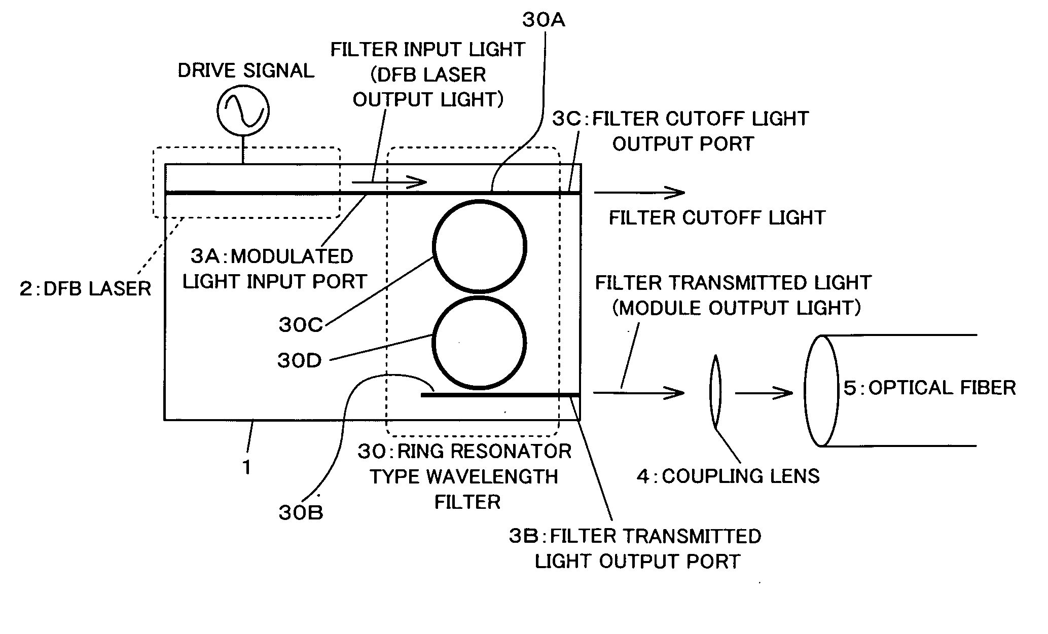
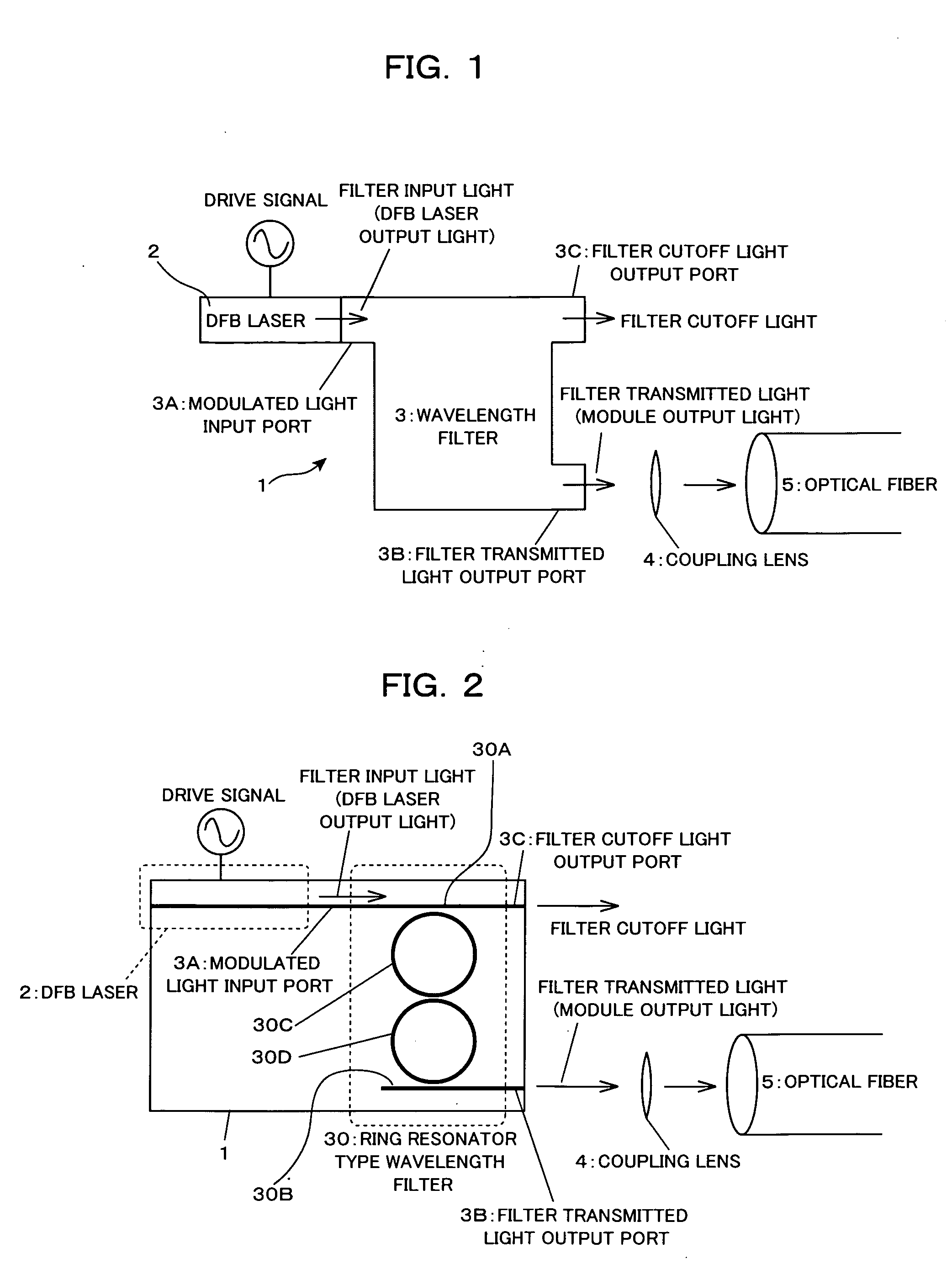
[0061] The optical transmitter according to the first embodiment is, for example, as shown in a conceptual diagram in FIG. 1, a low chirp directly modulated laser 1 as an optical transmitter module, including a DFB laser 2 as a single mode oscillation directly modulated laser and a wavelength filter 3 provided on a post-stage of the DFB laser 2.

[0062] Here, the DFB laser 2 is designed so as to be driven under the conditions of a high average light output (large direct current bias) and a low extinction ratio (small drive current amplitude), like a low chirp directly modulated laser according to the prior art.

[0063] Further, the filter properties of the wavelength filter 3 are set such that signal light (modulated light) directly modulated in and output from the DFB laser 2 is inputted thereto via a modulated light input port 3A, wherein light having a wavelength c...

second embodiment

[0109] Next, an optical transmitter according to a second embodiment of the present invention will be explained with reference to FIG. 10.

[0110] As shown in FIG. 10, the configuration of the optical transmitter (optical transmitter module; low chirp directly modulated laser) according to the present embodiment resembles the first embodiment (refer to FIG. 2) in that the DFB laser and the ring resonator type wavelength filter are used but differs in that the wavelength filter 30 is formed on a planer lightwave circuit (PLC) substrate 60 made of a silica glass material and a DFB laser 2A is integrated in a hybrid manner using the PLC substrate 60 as a platform. Incidentally, in FIG. 10, the same components as those in the first embodiment described above (refer to FIG. 2) are assigned with the same symbols.

[0111] Additionally, here, as the planer lightwave circuit (PLC) substrate 60, one made of silica glass is used, however, the substrate is not limited to this, and it is only nece...

third embodiment

[0125] Next, an optical transmitter according to a third embodiment of the present invention will be described with reference to FIG. 11.

[0126] As shown in FIG. 11, the optical transmitter (optical transmitter module; low chirp directly modulated laser) according to the present embodiment differs from the first embodiment described above in that a light absorption region 6 is provided, which is capable of absorbing the filter cutoff light output from the filter cutoff light output port 3C (or the optical waveguide connected to the filter cutoff light output port 3C) of the wavelength filter 30. Incidentally, in FIG. 11, the same components as those in the first embodiment (refer to FIG. 2) described above are assigned with the same symbols.

[0127] Here, in the light absorption region 6, it is only necessary to arrange a material whose absorption end wavelength is positioned on a longer-wavelength side than the longest wavelength of the filter cutoff light so that light having all o...


PUM


Abstract

In an optical transmitter comprising a directly modulated laser and a wavelength filter provided on a post-stage of the directly modulated laser, the wavelength filter has a modulated light input port for inputting modulated light output from the directly modulated laser, a filter transmitted light output port for outputting light having a wavelength included in a filter transmission band among the modulated light as filter transmitted light, and a filter cutoff light output port provided separately from the modulated light input port and the filter transmitted light output port and outputting light having a wavelength included in a filter cutoff band among the modulated light as filter cutoff light, and the peak of the filter transmission band is set on a shorter-wave side from the peak of the spectrum of modulated light output from the directly modulated laser.

Description

CROSS REFERENCE TO RELATED APPLICATIONS [0001] This application is based on and hereby claims priority to Japanese Application No. 2005-330372 filed on Nov. 15, 2005 in Japan, the contents of which are hereby incorporated by reference. BACKGROUND OF THE INVENTION [0002] (1) Field of the Invention [0003] The present invention relates to an optical transmitter used in an optical communication system, and for example, to an optical transmitter provided with a directly modulated laser. [0004] (2) Description of Related Art [0005] An optical transmitter module provided with a directly modulated laser (DML) is simple in comparison with one using an external modulator and has advantages that the cost is low, the space is saved, and the consumed power is small. [0006] However, the DML has large wavelength chirping in comparison with one using an external modulator and has a disadvantage that the transmission distance is reduced as a result. [0007] Here, the wavelength chirping means wavelen...

Claims


Application Information

Patent Timeline
Patent Type & Authority Applications(United States)
IPC IPC(8): H04B10/04G02B6/12G02B6/122H01S5/50
CPCG02B6/12004G02B6/12007G02F1/3519H01S5/0078H04B10/25H04B10/503H04B10/504H04B10/58
Inventor AKIYAMA, SUGURUYAMAMOTO, TSUYOSHI
Owner FUJITSU LTD
Why Eureka
Try Eureka