Centrifugal drier

A dryer, centrifugal technology, used in centrifuges, dryers, drying solid materials, etc.

Active Publication Date: 2010-03-17
GALA INDUSTRIES INC
View PDF5 Cites 8 Cited by
  • Summary
  • Abstract
  • Description
  • Claims
  • Application Information

AI Technical Summary

Problems solved by technology

In addition, the holes can only be punched precisely in the screen in order to connect e.g. delivery cylinders

Method used


Image

  • Centrifugal drier
  • Centrifugal drier
  • Centrifugal drier

Examples


Embodiment Construction

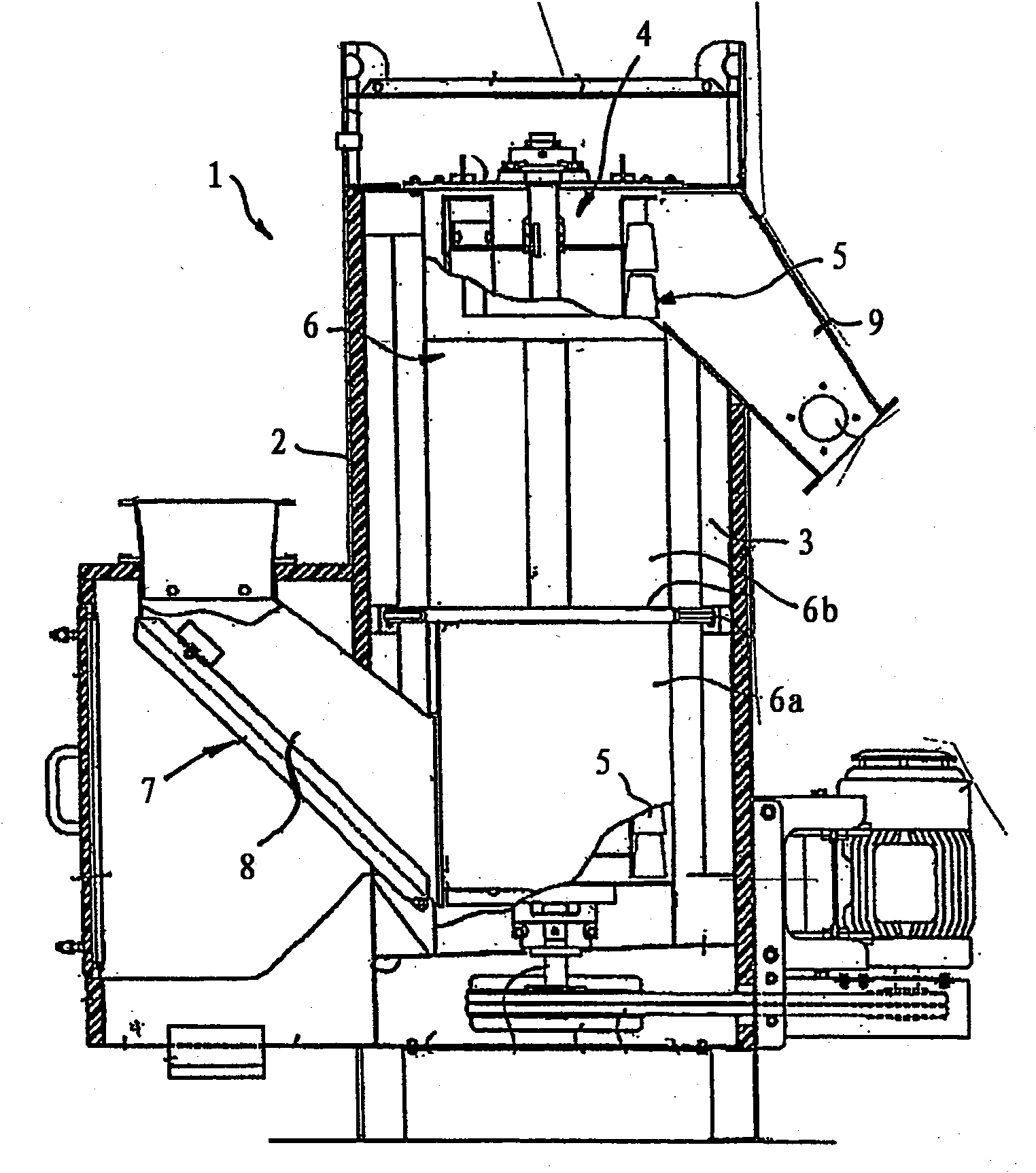
[0031] figure 1 The illustrated centrifugal dryer 1 comprises an overall—roughly speaking—cylindrical housing 2 , which is closed by a door provided on the housing side, through which the interior 3 of the housing 2 is accessible. Arranged in the interior 3 of the housing 2 is a rotor 4 , which can be driven in rotation about a vertical axis of rotation by means of a drive motor (not shown in detail). Such as figure 1 As shown, the rotor 4 includes a plurality of vane-like conveying elements 5 which protrude from the central axis of rotation and guide the granulate / process water mixture in the centrifugal dryer 1 from the bottom up into the inner space 3 of the housing. The conveying elements 5 protruding from the axis of rotation can in principle be designed in different ways, for example in the form of planar, curved or curved plates or in the form of helically curved parts or other shaped conveying elements.

[0032] In this respect, the rotor 4 is surrounded in the inner...


PUM


Abstract

The invention relates to a centrifugal drier for separating granulated materials from process water, said drier comprising a housing, a rotor arranged in the housing, and a sieve surrounding the rotoron the periphery thereof and comprising at least one porous sieve element which is bent around at least one sieve carrier ring and detachably fixed thereto. According to the invention, the sieve consists of a plurality of sieve elements which overlap each other in the peripheral direction and are fixed to the sieve carrier ring by at least one clamping belt surrounding the overlapping sieve elements on the periphery thereof. Fundamentally different, curved, flexible and / or elastic tractive elements can be arranged around the sieve elements as clamping belts, said tractive elements being tightened and thereby holding the sieve elements together.

Description

technical field [0001] The invention relates to a centrifugal dryer for separating particulate matter from process water, having a housing, a rotor arranged in the housing and a screen surrounding the rotor on the circumferential side, wherein the screen has at least one perforated screen element , which is bent around at least one screen support hoop and is releasably fastened to the support hoop. Background technique [0002] Through the centrifugal dryer behind the underwater granulator, the plastic granules produced by underwater granulation are continuously separated from the production water of the granulation equipment. Such centrifugal dryers, which can optionally also be used to separate other particulate matter from corresponding liquids, generally have a vertical rotor, which is driven in rotation around a vertical rotor shaft and is driven from bottom to top by means of mostly blade-shaped conveying elements. Conveying of pellets or pellet-water mixture, wherein...

Claims


Application Information

Patent Timeline
Patent Type & Authority Applications(China)
IPC IPC(8): F26B5/08B04B5/12
CPCF26B17/24F26B5/08B04B5/12B04B7/16
Inventor 于尔根·费尔特尔托马斯·巴斯克马库斯·彼得斯克里斯托弗·马斯曼斯
Owner GALA INDUSTRIES INC
Why Eureka
Try Eureka