Coolant valve for a vehicle

A coolant valve and coolant technology, which is used in engine cooling, coolant flow control, valve devices, etc., and can solve the problems of high bearing capacity, low driving torque of valve elements, and low cost.

Pending Publication Date: 2021-04-27
ILLINOIS TOOL WORKS INC
View PDF8 Cites 0 Cited by
  • Summary
  • Abstract
  • Description
  • Claims
  • Application Information

AI Technical Summary

Problems solved by technology

However, the known seals entail considerable costs
[0005] A problem with known sealing arrangements for coolant valves is that, firstly, the sealing arrangement is reliable against the valve element and thus the sealing action is

Method used


Image

  • Coolant valve for a vehicle
  • Coolant valve for a vehicle
  • Coolant valve for a vehicle

Examples


Embodiment Construction

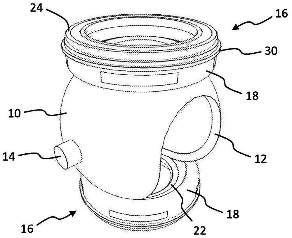
[0046] figure 1 The coolant valve shown has a valve element 10 , in the example shown a spherical valve element 10 . In the example shown, the valve element has an orifice 12 and bearing journals 14, which are arranged on opposite sides and at the figure 1 Only one bearing journal can be seen in . The valve element 10 is pivotably mounted in the housing via a bearing journal 14 (for illustration reasons in figure 1 not shown in more detail). The valve element can be pivoted, for example, by an electric drive which is controlled by a control device. figure 1 The coolant valve shown is installed in the cooling circuit of a vehicle such as a car or truck with an internal combustion engine and / or an electric motor. The housing has for example three coolant ports, it is possible, for example, that the coolant port connected to the coolant inlet is connected by pivoting of the valve element 10 to the first coolant port or the second of the two further coolant ports. Coolant por...


PUM


Abstract

A coolant valve for a vehicle includes a housing having a plurality of coolant ports, a valve element arranged in an adjustable manner in the housing in order to connect or disconnect coolant ports, and at least one seal arrangement. The seal arrangement bears in a sealing manner against the housing on one side and in a sealing manner against the valve element on the other side, the seal arrangement having a carrier element made of a first material and a sealing element made of a second material, the second material being softer than the first material. The sealing element has a first sealing lip bearing against the valve element and the carrier element having a supporting portion. The first sealing lip protrudes beyond the supporting portion with a free end, and the first sealing lip is pressed against the supporting portion when coolant flows through the coolant valve.

Description

technical field [0001] The present invention relates to a coolant valve for a vehicle, the coolant valve comprising: a housing having a plurality of coolant ports; and at least one sealing device arranged in the region of the at least one coolant port, which seals against the housing on one side and against the valve element on the other side in a sealing manner. Background technique [0002] Coolant valves of the type described above are used in the coolant circuit of vehicles such as cars or trucks. These coolant valves are used, for example, to cool the internal combustion engine. For example, cooling liquid is led through the radiator via a bypass line during a warm-up phase of the internal combustion engine, and after reaching the operating temperature, in a manner dependent on the position of the valve element. In the case of the coolant valve it is also possible, in an application-dependent manner, for the coolant to flow through the coolant valve only temporarily, ...

Claims


Application Information

Patent Timeline
IPC IPC(8): F16K5/06F16K5/20F01P7/14
CPCF16K5/0678F16K5/208F01P2007/146F01P7/14
Inventor 莱纳·格拉姆斯托尔斯滕·豪克
Owner ILLINOIS TOOL WORKS INC
Why Eureka
Try Eureka