Linkage device for bridges

A linkage device and bridge technology, applied in bridges, bridge parts, bridge construction, etc., can solve the problems of long production and processing cycle, high price, leakage, etc., achieve good elasticity and damping, mature technology, and convenient adjustment Effect

Active Publication Date: 2015-04-29
CHENGDU XINZHU ROAD & BRIDGE MASCH CO LTD
View PDF6 Cites 0 Cited by
  • Summary
  • Abstract
  • Description
  • Claims
  • Application Information

AI Technical Summary

Problems solved by technology

This type of device has relatively high requirements on processing accuracy and materials, and is often expensive, and the production and processing cycle is relatively long; moreover, the liquid medium in it often leaks due to the problem of sealing technology.

Method used


Image

  • Linkage device for bridges
  • Linkage device for bridges
  • Linkage device for bridges

Examples


Embodiment 1

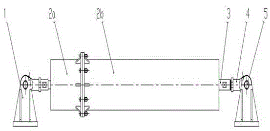
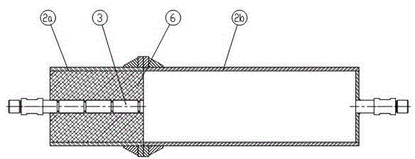
[0023] Embodiment 1: as figure 1 , 2 As shown, a linkage device for a bridge includes a detachably butted rubber casing 2a and a connecting cylinder 2b, the rubber casing 2a is filled with an elastomer material 6 and a connecting shaft 3 is arranged axially in the center , the elastomer material 6 is firmly bonded to the inner wall of the rubber casing 2a and the surface of the connecting shaft 3, and the connecting shaft 3 protrudes from the left end of the rubber casing 2a to thread the joint bearing 4, and the joint bearing 4 rotates through the pin shaft 5 Connected to the connecting lug 1, the right end of the connecting cylinder 2b is fixedly connected to the connecting shaft 3, the right end of the connecting shaft 3 is threaded to the joint bearing 4, and the joint bearing 4 is rotatably connected to the connecting lug 1 through the pin shaft 5.

[0024] The rubber-covered cylinder 2a and the connecting cylinder 2b are respectively provided with flanges at the ends, a...

Embodiment 2

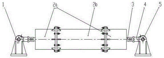
[0025] Embodiment 2: as image 3 , 4 As shown, a linkage device for a bridge includes a connecting cylinder 2b and two rubber casings 2a detachably butted at both ends of the connecting cylinder 2b, each rubber casing 2a is filled with an elastomer material 6 and in the center A connecting shaft 3 is arranged in the axial direction, and the elastomer material 6 is firmly bonded to the inner wall of the rubber casing 2a and the surface of the connecting shaft 3, and the connecting shaft 3 extends out of the left end of the rubber casing 2a on the left and the rubber covering on the right. The right end of the cylinder 2a is then threaded on the protruding end of the joint bearing 4, and the joint bearing 4 is rotatably connected to the connecting lug 1 through the pin shaft 5.

[0026] Both ends of the connecting cylinder 2b and one end of the two rubber-coated cylinders 2a are provided with flanges, and bolts are used to fix the flanges on the ends of the connecting cylinder ...


PUM


Abstract

The invention discloses a linkage device for bridges. The linkage device comprises rubber-coating cylinders and a connecting cylinder which are detachably connected in butt joint. The rubber-coating cylinders are filled with elastomer materials inside and provided with a connecting shaft axially arranged at the center, the end, extending out of the left end of the left rubber-coating cylinder, of the connecting shaft is connected with a knuckle bearing in a threaded manner, the knuckle bearing is rotatably connected to a connecting lug through a pin roll, the connecting shaft is fixedly connected at the right end of the connecting cylinder, the right end of the connecting shaft is connected with a knuckle bearing in a threaded manner, and the knuckle bearing is rotatably connected to a connecting lug through a pin roll. The linkage device for the bridges has the advantages that relative movement occurs between a cylinder wall of the rubber-coating cylinder and the connecting shaft under the action of axial stretching or contracting, so that the elastomer materials are subjected to shearing action, and kinetic energy is converted into internal energy of the elastomer materials to achieve the effect of buffering.

Description

technical field [0001] The invention relates to the technical field of bridges, in particular to a linkage device for bridges. Background technique [0002] When the bridge is in use, the structure needs to be able to adapt to the deformation caused by thermal expansion and contraction of the material, and it is not expected that the structure will produce excessive movement due to vehicle impact, braking, and earthquakes. [0003] Therefore, devices such as viscous dampers and speed locks are installed on many bridges to control the movement of the bridge structure. This type of device has relatively high requirements on processing accuracy and materials, and is often expensive, and the production and processing cycle is relatively long; moreover, the liquid medium in it often leaks due to the problem of sealing technology. Contents of the invention [0004] The purpose of the present invention is to provide a linkage device for bridges with simple structure, reliable pe...

Claims


Application Information

Patent Timeline
Patent Type & Authority Patents(China)
IPC IPC(8): E01D19/04
Inventor 黄菲张松游珏涛
Owner CHENGDU XINZHU ROAD & BRIDGE MASCH CO LTD
Why Eureka
Try Eureka