Adjustable Length Discharge Joint for High Pressure Applications

a discharge joint and adjustable technology, applied in the direction of screw threaded joints, mechanical equipment, manufacturing tools, etc., can solve the problems of inconvenient installation, increased weight and area required for these connections, and inability to manufacture and assembly the installation

Inactive Publication Date: 2009-10-22
HALLIBURTON ENERGY SERVICES INC
View PDF11 Cites 79 Cited by
  • Summary
  • Abstract
  • Description
  • Claims
  • Application Information

AI Technical Summary

Benefits of technology

[0004]Accordingly there is disclosed herein an adjustable length straight discharge joint, which is adapted for use in high-pressure connections. The ability to adjust the length of a high-pressure connection allows a fixed installation to be made up when space or weight restrictions would not allow swivel joints to give enough degrees of freedom between components. When the disclosed apparatus is employed, fabrication and assembly of fixed high-pressure assemblies will be much easier and quicker, as the tolerance stack up will be of less concern.
[0009]Therefore, the disclosed embodiments may advantageously provide a novel adjustable length discharge joint for high-pressure applications that may be successfully employed in situations where space or weight restrictions would not allow swivel joints to give enough degrees of freedom between components and in situations where tolerance stack up is an issue. The above and other features of this invention will be fully understood from the following description and the accompanying drawings.

Problems solved by technology

What these installations lack, however, is a way to compensate for the differences in distances and orientations between the various components within the installation.
However, in many applications the added weight and area required for these connections is prohibitive.
This significantly slows down the fabrication and assembly of the installation, and results in the loss of significant amounts of time, labor, and financial resources.

Method used


Image

  • Adjustable Length Discharge Joint for High Pressure Applications
  • Adjustable Length Discharge Joint for High Pressure Applications
  • Adjustable Length Discharge Joint for High Pressure Applications

Examples


Embodiment Construction

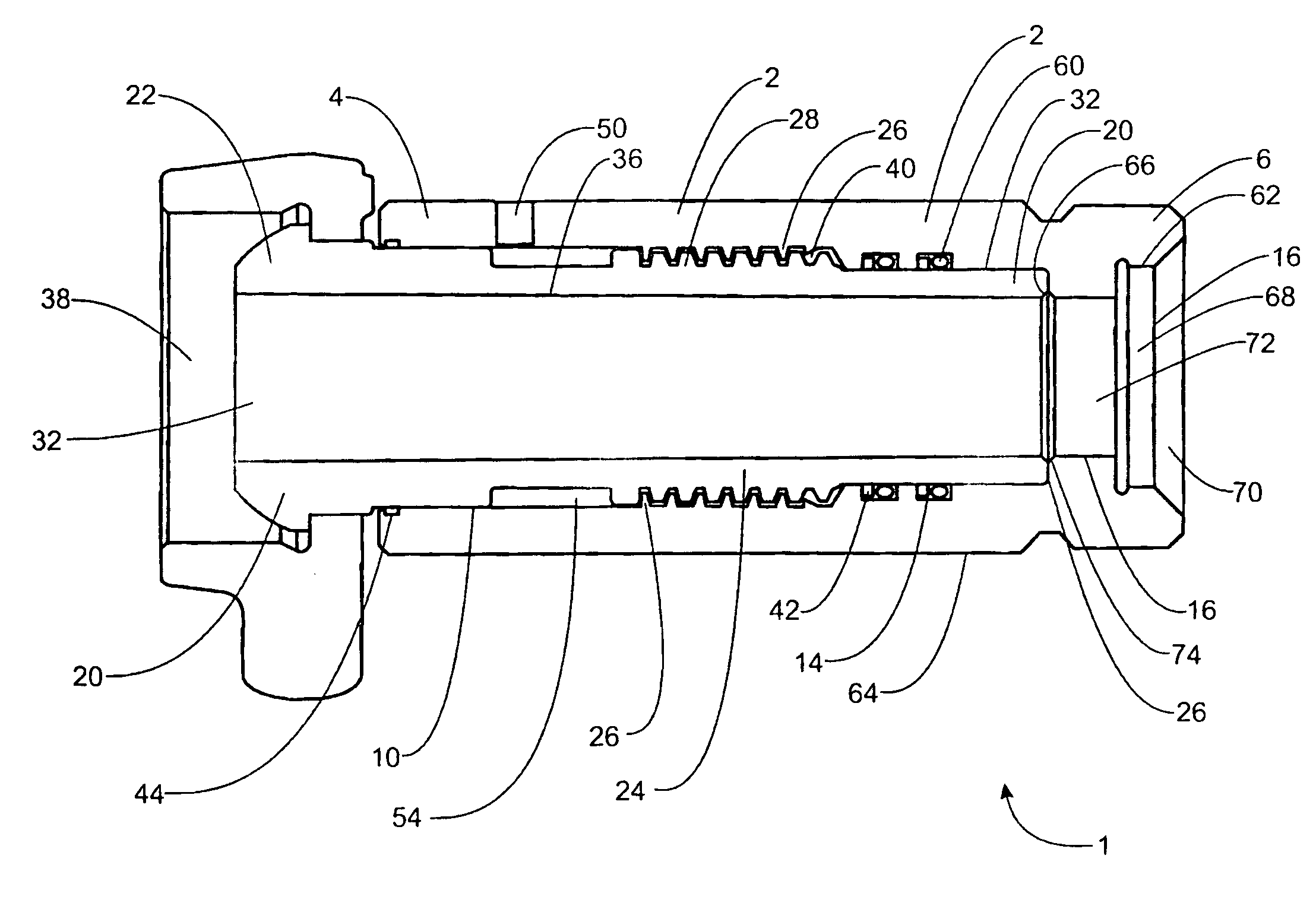
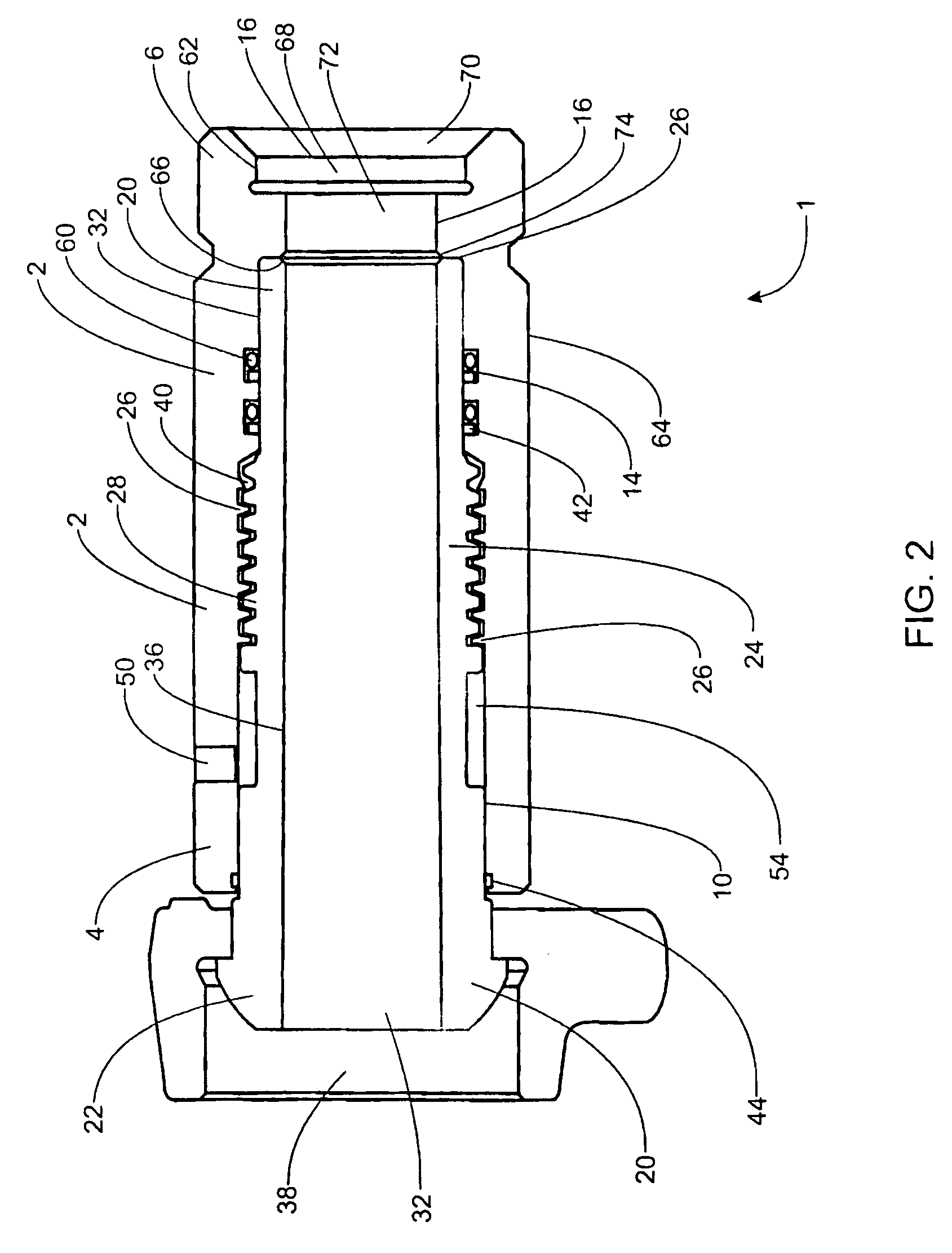
[0017]While adjustable joint assemblies have been designed for connecting rigid components within low-pressure fluid delivery installations, e.g. up to approximately 500 psi, no apparatus currently exists for successfully connecting rigid components within high-pressure installations where space and weight may be an issue and tolerance stack up can cause binding and sealing problems. Adjustable installations designed for low-pressure fluid delivery assemblies are generally not sufficient to withstand the radial and axial forces within high-pressure installations. Seal design, wall thickness, end connection, and material selection are all dependent on the pressure rating. As such, assemblies designed for lower pressure installations would fail from any of these criteria when used in high-pressure environments. As such, a need still exists for an adjustable length joint for high-pressure applications.

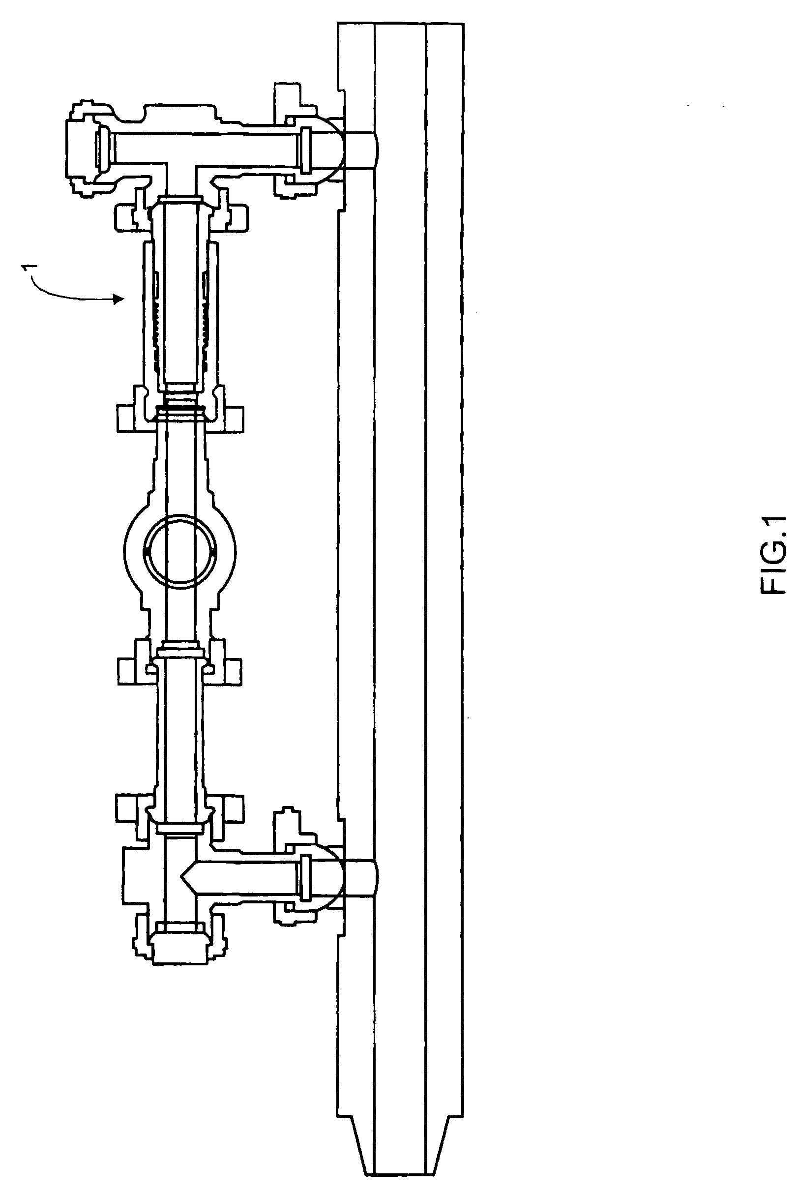
[0018]With reference to FIG. 1, the environment in which the illustrated embodiments ...


PUM

PropertyMeasurementUnit
pressureaaaaaaaaaa
pressureaaaaaaaaaa
pressureaaaaaaaaaa

Abstract

An adjustable length joint for high-pressure applications is described that includes rigid inner and outer tubes; both having passages there through. The rigid outer tube has at least one peripheral ring groove within its inner wall. The tubes have threads, which are adapted to adjustably engage with one another securely at a working pressure of at least about 10,000 psi. The rigid inner tube and the rigid outer tube are rotatable to enable adjustable engagement between the threads. The joint also includes an O-ring seated in each of the at least one peripheral ring grooves. When the rigid inner tube and the rigid outer tube are held in a selectable position, the first thread and the second thread overlap a sufficient distance necessary for the first thread and the second thread to withstand the forces exerted by the internal pressure within the joint at the working pressure.

Description

BACKGROUND[0001]This invention relates generally to adjustable length discharge joint assemblies and more particularly, but not by way of limitation, to adjustable length discharge joints suitable for high-pressure connections or installations where tolerance stack up is an issue.[0002]At a site where an oil or gas well has been drilled, there is often the need for conveying substances at high pressure, i.e. 10,000-20,000 pounds per square inch (“psi”), between two fixed components within the fluid delivery installation, which are spaced at different distances and orientations relative to each other at a well site. Assemblies having parallel-connected rigid interconnections were developed to facilitate the delivery of these fluids under high-pressure. These rigid interconnections facilitate relatively rapid fluid delivery while allowing easily controllable shutoff should a portion of the installation be damaged or require maintenance. What these installations lack, however, is a way...

Claims


Application Information

Patent Timeline
Patent Type & Authority Applications(United States)
IPC IPC(8): F16L15/02F16L27/12B23P11/00
CPCE21B17/02E21B17/042Y10T29/49826F16L27/125F16L15/04F16L27/1275
Inventor BULL, BRADKENDRICK, WILLIAM D.
Owner HALLIBURTON ENERGY SERVICES INC
Why Eureka
Try Eureka