Adjustable support tool for vertical and horizontal mounting

a technology of adjustable support and mounting rods, which is applied in the direction of machine supports, manufacturing tools, rod connections, etc., can solve the problems of rods being oxidized over time, causing confusion for users, and the drawbacks of conventional adjustable tools

Inactive Publication Date: 2007-11-06
WANG DENNIS H
View PDF5 Cites 80 Cited by
  • Summary
  • Abstract
  • Description
  • Claims
  • Application Information

AI Technical Summary

Benefits of technology

[0006]An adjustable support tool for either vertical or horizontal mounting is disclosed. The adjustable support tool comprises a rod slidably received by a tube. The rod has depressions formed thereon. A threaded portion is engaged to the tube as an external sleeve, or can be formed as threads on the tube, and a hand grip tightener is turnably engaged to the threaded sleeve for adjusting their overall length. A ratchet housing is resiliently engaged to the hand grip tightener. The ratchet housing has a ratchet for securely engaging to one of the depressions, a wheel spring for rollably engaging to another one of the depressions, a safety lock pivotally engaged to the ratchet housing for prevent access to the ratchet when locked. When the rod is slided, the wheel spring pushes up the ratchet from its underside to loosen its engagement. The loosened ratchet allows the rod to slide more smoothly, while protecting the painted surface on the rod. Both the ratchet and threaded sleeve provide adjustment to the overall length of the support tool.

Problems solved by technology

Such conventional adjustable tools still have their drawbacks.
First, in the Huang patent, the shaft (50) often fails to provide a clear indication as to whether the lever is engaged or disengaged, thus creating confusion to the users.
Also, as in both Huang and Shiau patents, a secondary, or fine, adjustment other than the positioning of the depressions (12) is often needed by the user, since the positions of the depressions are fixed and cannot accommodate too much variation.
Last but not least, the pawl tends to scratch the paint off the surface of the rod when the rod is moved, thus causing the rod to be oxidized over time.

Method used


Image

  • Adjustable support tool for vertical and horizontal mounting
  • Adjustable support tool for vertical and horizontal mounting
  • Adjustable support tool for vertical and horizontal mounting

Examples


Embodiment Construction

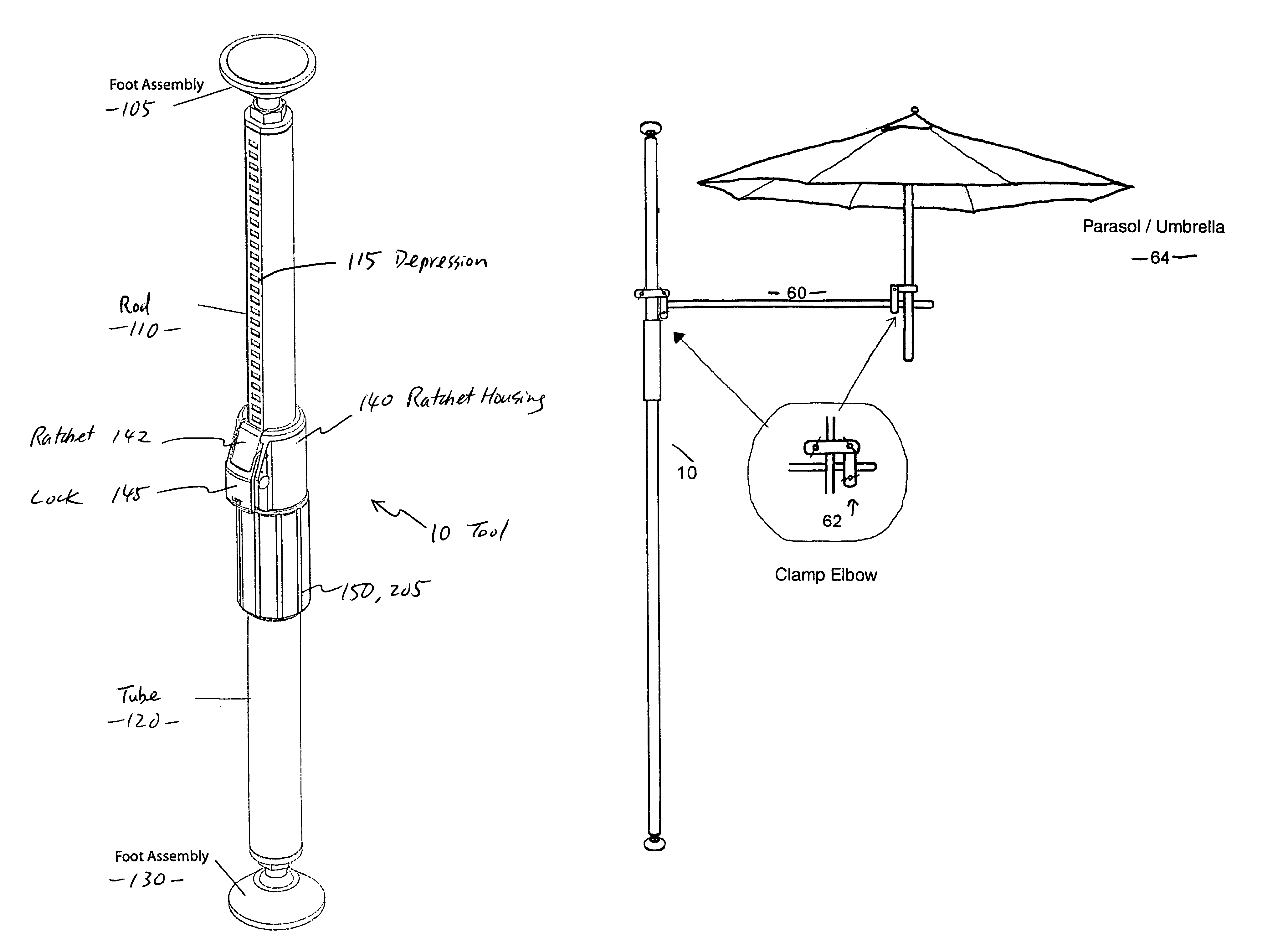
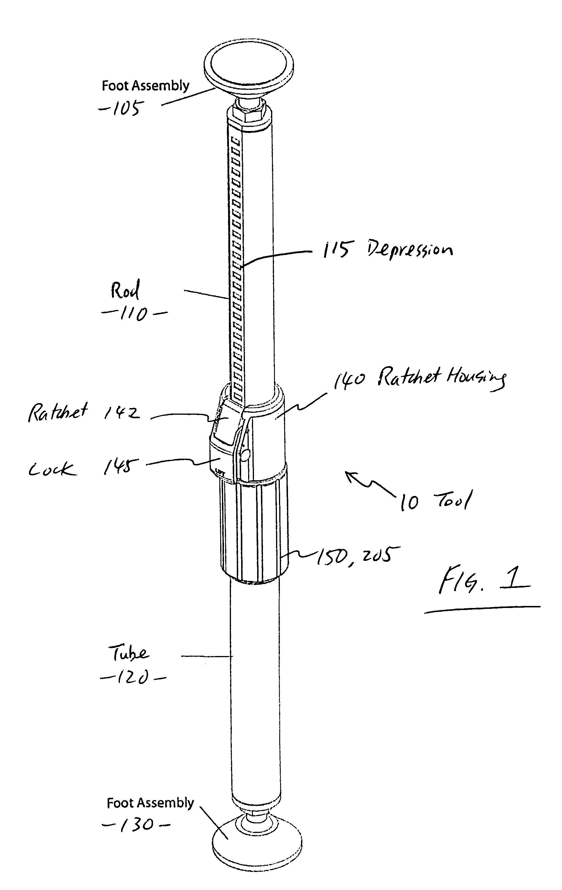
[0020]Referring first to FIGS. 1-5, an adjustable support tool 10 for vertical and horizontal mounting in accordance with the present invention is disclosed. The tool 10 has a rod 110 slidably received in a tube 120 including an upper portion having a number of depressions 115 formed therein. The rod 110 and the tube 120 each includes one end having a foot assembly 105, 130, respectively, which is movably secured thereon for engaging the tube 10 to generally flat surfaces. For vertical mounting, the foot assembly 105, 130 can be adjusted to engage with the ceiling and floor surfaces, although either end may be the upper end. For horizontal mounting, the foot assembly 105, 130 can be adjusted to engage with vertical sidewall surfaces. The foot assembly 105, 130 may be rotatably or pivotally secured to the rod 110 or the tube 120, for allowing the foot assembly pieces to be solidly and stably engaged with the contact surfaces.

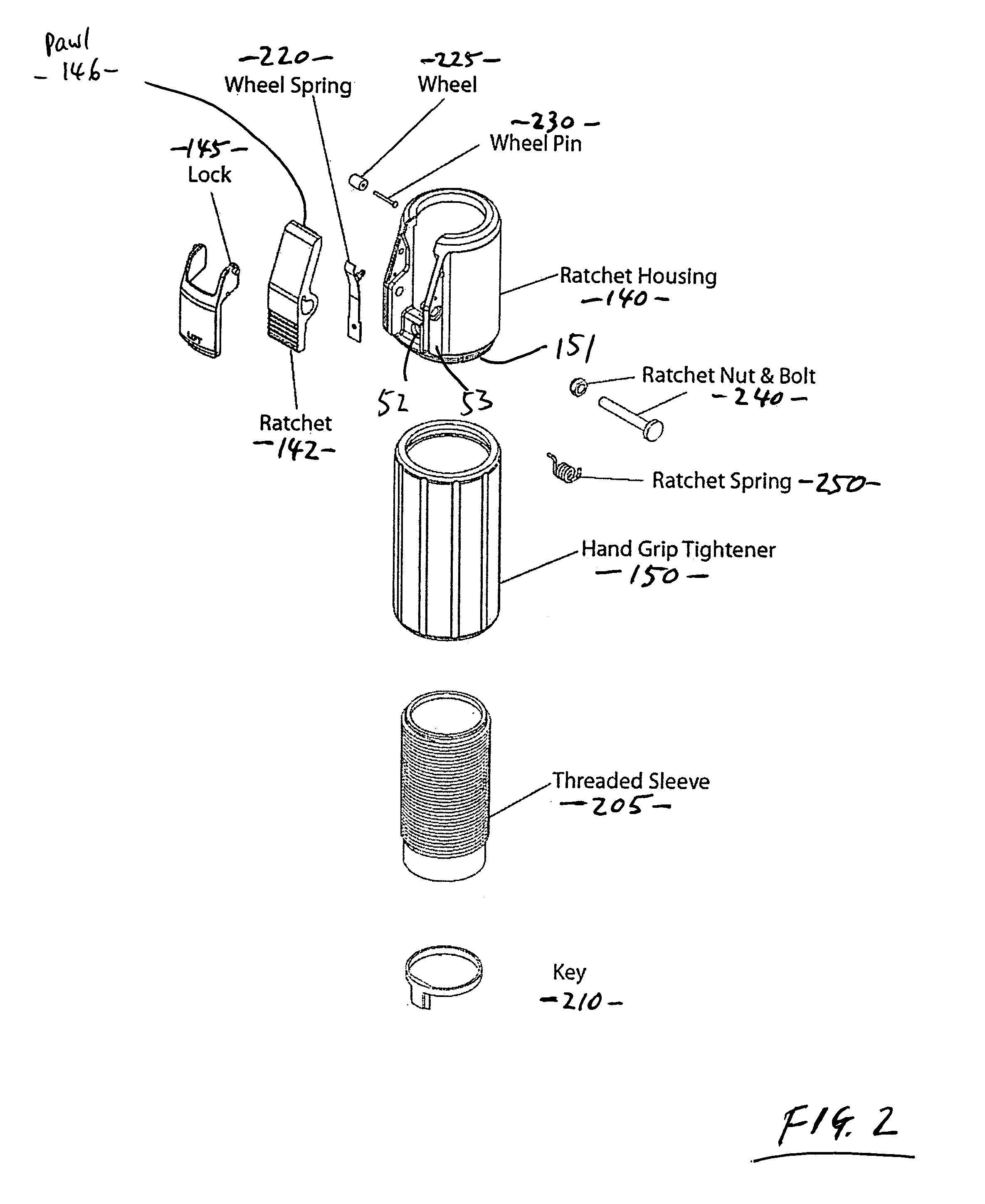
[0021]Opposite to the foot assembly 130 on the tube 120, a ...


PUM


Abstract

An adjustable support tool for either vertical or horizontal mounting. The adjustable support tool comprises a rod slidably received by a tube. The rod has depressions formed thereon. A threaded portion is coupled to the tube and a hand grip tightener is turnable engaged to the threaded portion for adjusting their overall length. A ratchet housing is resiliently engaged to the hand grip tightener. The ratchet housing has a ratchet for securerly engaging to one of the depressions, a wheel spring for rollably engaging to another one of the depressions, a safety lock pivotally engaged to the ratchet housing for prevent access to the ratchet when locked. When the rod is slided, the wheel spring pushes up the ratchet from its underside to loosen its engagement. The loosened ratchet allows the rod to slide more smoothly, while protecting the painted surface on the rod. Both the ratchet and threaded portion provide adjustment to the overall length of the support tool.

Description

RELATED APPLICATION[0001]This application claims benefit under 35 U.S.C. § 119(e) of U.S. provisional application No. 60 / 554,978, filed Mar. 19, 2004, entitled ADJUSTABLE SUPPORT TOOL FOR VERTICAL AND HORIZONTAL MOUNTING, the entirety of which is hereby incorporated herein by reference.ART BACKGROUND[0002]Adjustable support tools have become quite common for home and industrial use. One example of such adjustable tool is disclosed by Huang in U.S. Pat. No. 6,247,882 (hereinafter “Huang”), issued on Jun. 19, 2001, entitled “CARGO BRACING DEVICE,” and another example of an adjustable tool is disclosed by Shiau in U.S. Pat. No. 5,988,963 (hereinafter “Shiau”), issued on Nov. 23, 1999, entitled “CARGO POSITIONING FRAME.” Both prior patents are incorporated by reference as if fully set forth herein.[0003]The Huang patent discloses a bracing device including a rod slidably received in a tube and having a number of depressions. A lever (35) is pivotally secured to the tube and has a pawl (...

Claims


Application Information

Patent Timeline
Patent Type & Authority Patents(United States)
IPC IPC(8): E04G25/00A45B7/00A45B23/00A45B25/08B25B13/46E04F10/06F16B7/10F16M11/00F16M11/28
CPCA45B7/005A45B23/00E04F10/0681F16M11/28F16M13/027A45B25/08A45B2023/005A45B2023/0068F16M2200/066F16B7/105F16M2200/028E04F10/0603
Inventor WANG, DENNIS H.
Owner WANG DENNIS H
Why Eureka
Try Eureka