Thin walled, two component cartridge casing

Inactive Publication Date: 2007-09-20
TECH CORPORATION CO LTD
View PDF2 Cites 165 Cited by
  • Summary
  • Abstract
  • Description
  • Claims
  • Application Information

AI Technical Summary

Benefits of technology

[0038]Using only two pieces to form the supporting casing members provides an advantage over other prior art processes because it permits the use of a sheet metal stamping-type process for the outer member, which is simpler than the common casing production process wherein a thick metal disk must be drawn and stretched in several separate operations to provide The casing with a thick base and a thin sidewall. The use of a thin walled, outer shell or sleeve of adequate strength surrounding a separate internal reinforcing plug can closely mimic the function of existing brass or steel one-piece casings, while providing a number of advantages over prior art casings. First, the outer component in the current invention can be produced from a thin sheet of metal e.g. 0.012-0.025 inches of 300 series stainless, rather than the thick plate e.g. 0.150-0.200 inches as typically used for an equivalent normal ca

Problems solved by technology

As observed in U.S. Pat. No. 2,774,283 by Harvey, the bolt face of such a typical weapon supports and rests against the base or head of the cartridge but does not completely provide support for sealing-in the gases.
The large number of steps in the process and the scrap produced, e.g. during machining the extractor groove, substantially add to the end item cost.
However, in the smaller sizes used in rifles, machine guns and other man-portable high velocity systems, aluminum has not been shown practical.
Under the high pressures and physical stresses encountered in such systems, aluminum has been shown to catastrophically fail in the event of even minor material defects.
The failure mode often results in ignition of the aluminum, causing a “burn through” that can be hazardous to the user.
Numerous attempts have been made to mitigate this behavior through the use of coatings and ablative materials (e.g. U.S. Pat. No. 3,765,297 by Skochko et al), but those methods have not been shown to be fully reliable.
Similar configurations have been tried for high-pressure casings, but they have required heavier base cups to retain the high pressures and attachment to the plastic sidewall to the metallic base cup is a problem.
Under th

Method used


Image

  • Thin walled, two component cartridge casing
  • Thin walled, two component cartridge casing
  • Thin walled, two component cartridge casing

Examples


Embodiment Construction

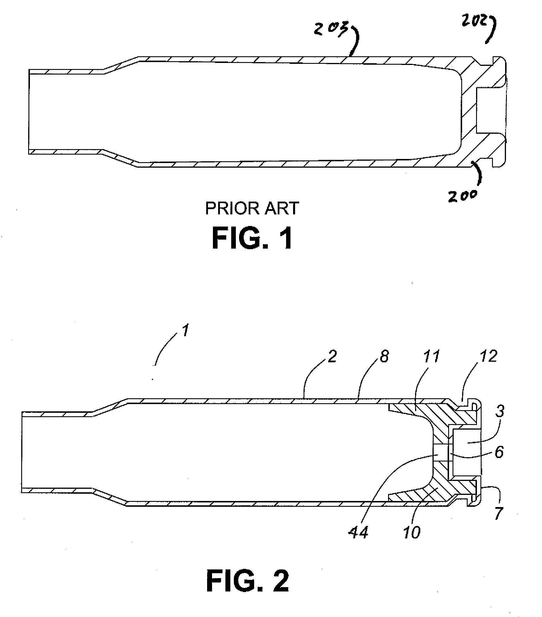
[0057]FIG. 1 shows a typical prior art cartridge case. A case of this type is formed by the progressive drawing of an initially thick “coin”, and as a result has a thick base member 200 at the head end 202 and a tapered cylindrical sidewall 203.

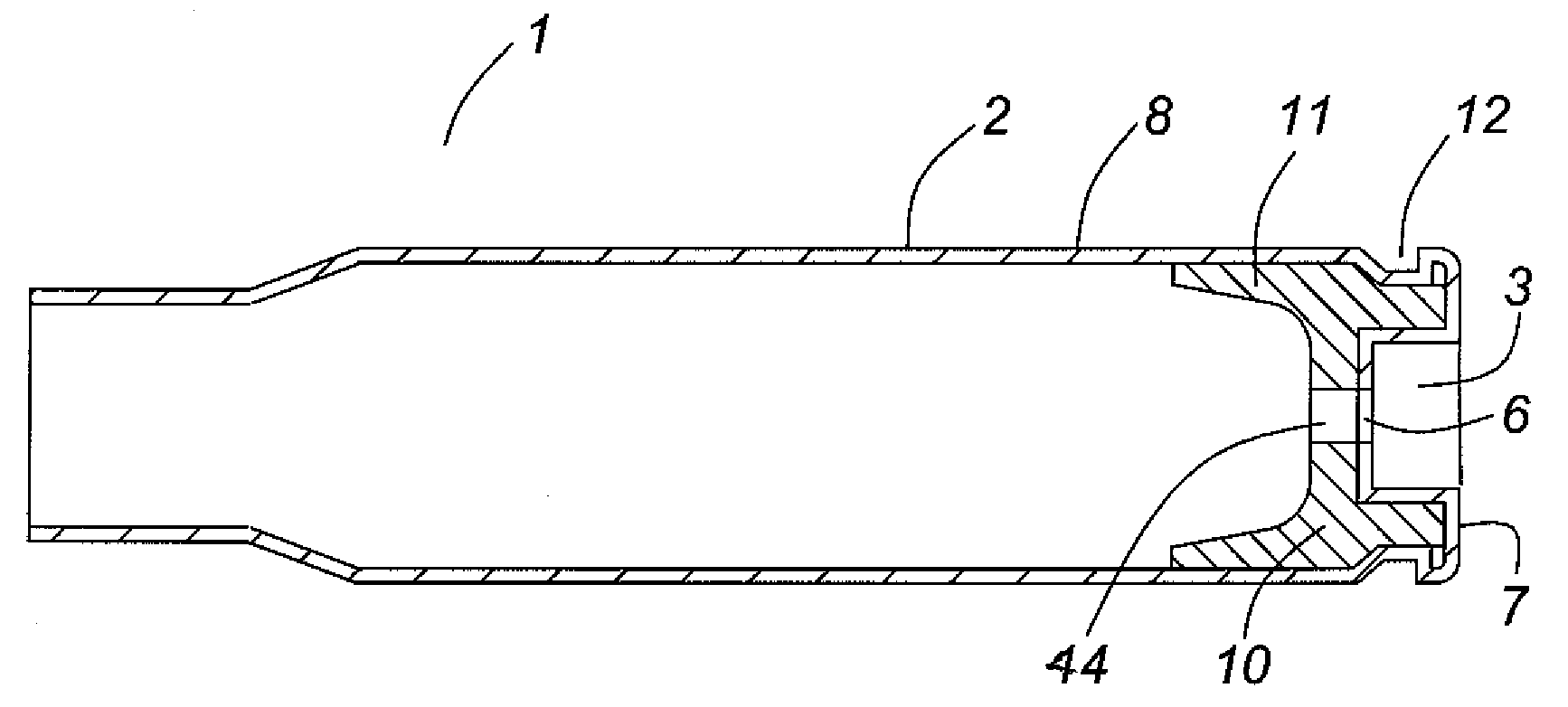
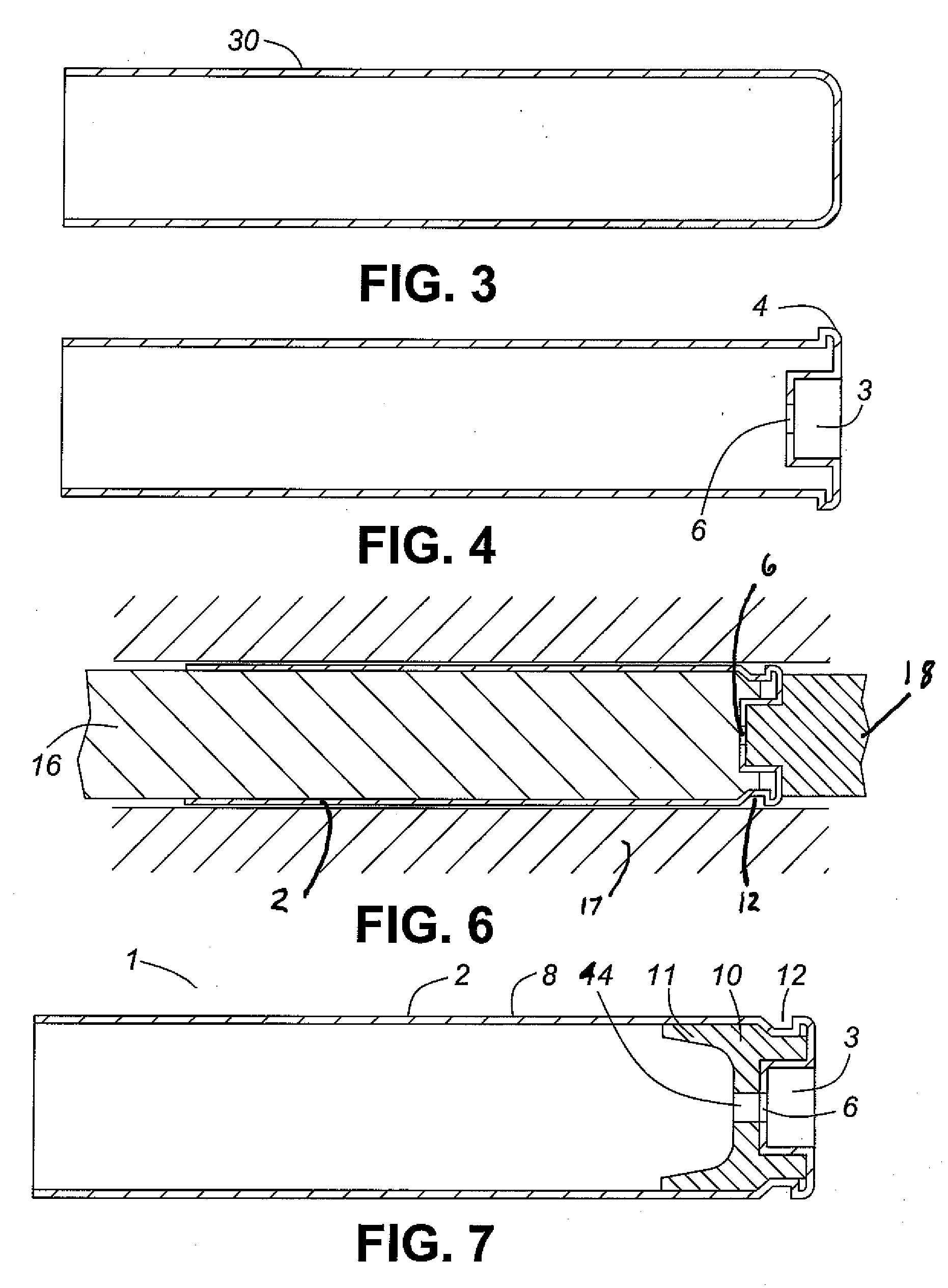
[0058]FIG. 2 depicts a first embodiment of the cartridge casing 1 of the current invention. A cartridge casing 1 is provided with an cylindrical outer case member 2 having a cylindrical sleeve portion 8 and an end member 7. A cylindrical reinforcing plug 10 is located at the head end 202 of the cartridge casing 1. The reinforcing plug 10 is arranged such that it will provide additional strength to the sleeve-like case member 8 in the base area of the cartridge casing 1 needed to withstand the higher stresses in that area of the cartridge casing 1 occurring as a result of gas expansion at the area of the cartridge casing 1 where the case 1 is not substantially supported by the barrel or bolt assembly.

[0059]In order to produce the outer case me...


PUM


Abstract

A cartridge or ammunition casing is made of two components, one forming the outer casing sleeve and head end and the other comprising a plug seated within the head end to protect the outer casing material from propellant gases. The outer cylindrical sidewall and end panel of the casing may be made of a material selected from the group consisting of stainless steel, steel, pre-coated carbon steel, brass or brass-type alloys, aluminum, hardened aluminum alloys, and suitable polymeric plastic material such as nylon derivatives and VECTRA™. The inner plug may be made of a material selected from the group consisting of aluminum, brass, steel, stainless steel, and suitable polymeric materials.

Description

[0001]This invention pertains to the field of ordnance. More particularly, it describes a cartridge casing and process for manufacturing the same which is directed towards cartridge casings typically used in small and artillery caliber ammunition.BACKGROUND OF THE INVENTION[0002]Cartridge casings used in small caliber to artillery caliber weapons provide the function of containing the other major components of the cartridge, including propellant, projectile or bullet and primer. In addition to being a container, the casing must expand slightly and act as a seal to prevent gases, generated by the propellant, from leaking from the forward or mouth end of the casing, along the sidewall of the casing, and through the breach or bolt face at the rear of the casing. The head end of the casing must also absorb the striking force of the firing pin without deforming excessively.[0003]In the case of rimless cartridges, a portion of the head end typically will extend beyond the support of the c...

Claims


Application Information

Patent Timeline
IPC IPC(8): F42B5/26
CPCF42B5/36
Inventor DITTRICH, WILLIAM A.
Owner TECH CORPORATION CO LTD
Why Eureka
Try Eureka