Optical recording medium and method for making

a technology of optical recording medium and optical recording medium, which is applied in the manufacture of optical recording carriers, record information storage, nuclear engineering, etc., can solve the problems of low productivity, long time, and the inability to use inexpensive resin substrates in the heating of the overall medium

Inactive Publication Date: 2001-06-05
TDK CORPARATION
View PDF20 Cites 57 Cited by
  • Summary
  • Abstract
  • Description
  • Claims
  • Application Information

AI Technical Summary

Benefits of technology

Another object of the present invention is to provide a novel and improved write-once type phase change optical recording medium which eliminates initializing operation and which cannot be rewritten at the same linear velocity as recording.

Problems solved by technology

However, the initialization step by laser beam irradiation takes a long time and causes low productivity.
Heating of the overall medium rejects the use of inexpensive resin substrates.
That is, resin substrates can be distorted upon heating for initialization, causing tracking errors.
The method of irradiating flash light is also low in productivity because several shots of irradiation are necessary to achieve full crystallization.
The bulk eraser, however, requires a time of several minutes for initializing optical recording discs of 12 cm in diameter.
While TeGeSb base materials are currently most widely used for phase change recording layers, it is believed that the initializing operation cannot be removed insofar as these materials are used.
The reason why the rate of erasure remains unstable upon rewriting immediately after initialization is that the formation of a AgSbTe.sub.2 or In--Te crystalline phase is incomplete.
However, in the duration from immediately after the formation of the recording layer to several times of rewriting, the rate of erasure remains unstable like prior art phase change type recording media.
More particularly, since reflectance is different between the region crystallized during formation and the region crystallized upon rewriting, the reflectance remains unstable until the rewritten regions are extended by increments throughout the entire surface of the recording layer.
However, in the embodiment of JP-A 106647 / 1996 wherein indium is not present in the AgSbTe.sub.2 film, but as the In--Sb film or In film, it becomes difficult for indium to bond with tellurium to form an In--Te crystalline phase.
As a result, the reflectance of the recording layer immediately after its formation is very low.
Since the low reflectance hinders focusing of a laser beam and hence, uniform heating, it becomes difficult to achieve uniform initialization.
Such a high indium content makes it difficult to form an In--Sb film as a crystalline one even if its thickness is increased.
There still arises the above-mentioned problem associated with initialization.
Although the reflectance of the recording layer before the mixing treatment is relatively high due to the crystallized antimony base thin films, the mixing treatment reduces the reflectance.
As a consequence, the initialization by irradiation of a laser beam requires a longer time.
More particularly, mixing of the antimony base thin film and the reactive thin film is possible when the recording power is applied, but crystallization is impossible in the region where mixing has occurred when the erasing power is applied to that region at the same linear velocity as in the recording mode.
If the value of x is too smaller, the indium content of the recording layer is relatively too low so that record marks become less amorphous, resulting in a lower degree of modulation and lower reliability.
If the value of y is too smaller, the silver content of the recording layer is relatively too low so that the recrystallization of record marks and hence, repetitive overwriting becomes difficult.
If the value of y is too larger, the silver content of the recording layer is relatively too high so that excess silver solely diffuses into the antimony phase during the mixing treatment.
This results in lower rewriting durability, less stability of both the record marks and the crystalline regions, and a loss of reliability.
If the value of x+y is too larger, it would become difficult to make the recording layer amorphous and it would become impossible to record signals.
If the value of z is too larger, it would become difficult to make the recording layer amorphous and it would become impossible to record signals.
If the M content of the recording layer is too high, the change of reflectance associated with a phase change becomes too small to provide a degree of modulation.
If the antimony base thin film is too thick, the reactive thin film must accordingly be thick and consequently, the recording layer as a while becomes too thick and increases light absorption.
If the number of both thin films is too large, the recording layer becomes too thick.
With a higher percent replacement, record marks are likely to crystallize, leading to a loss of reliability at elevated temperature.
With a higher percent replacement, record marks would become less stable with a resultant loss of reliability.
As a result, the recording layer becomes less reliable.
If the antimony base thin film is too thick, the reactive thin film must accordingly be thick and consequently, the recording layer as a while becomes too thick and increases light absorption.
If b is too small in formula (II-2), record marks are more likely to crystallize with a loss of reliability.
As a result, the waveform of read signals is deformed, adversely affecting the jitter and causing more errors.
A lower heat treatment temperature requires a longer time for crystallization whereas a higher heat treatment temperature can damage the substrate if it is a resin substrate such as polycarbonate.
A thickness beyond this range would provide no further improvement in reflectance and add to the cost.
As a consequence, the record mark formed by overwriting varies in length and breadth, and such variations lead to an increase of jitter which may cause an error.
Where mark edge recording of carrying information at either edge of a record mark is employed for high density recording purposes, the influence of the variation in length of a record mark becomes significant, resulting in more errors.
In a medium of the ordinary structure, however, if Ac / Aa.gtoreq.0.9, then the difference between the reflectance Rc from the medium at regions other than record marks and the reflectance Ra from the medium at record marks becomes undesirably smaller, resulting in a lower C / N ratio.
If the reflective layer is too thick, the absorption correcting effect would become insufficient.

Method used


Image

  • Optical recording medium and method for making
  • Optical recording medium and method for making

Examples


example 1

In--Ag--Te--Sb System (Sb thin film.fwdarw.reactive thin film)

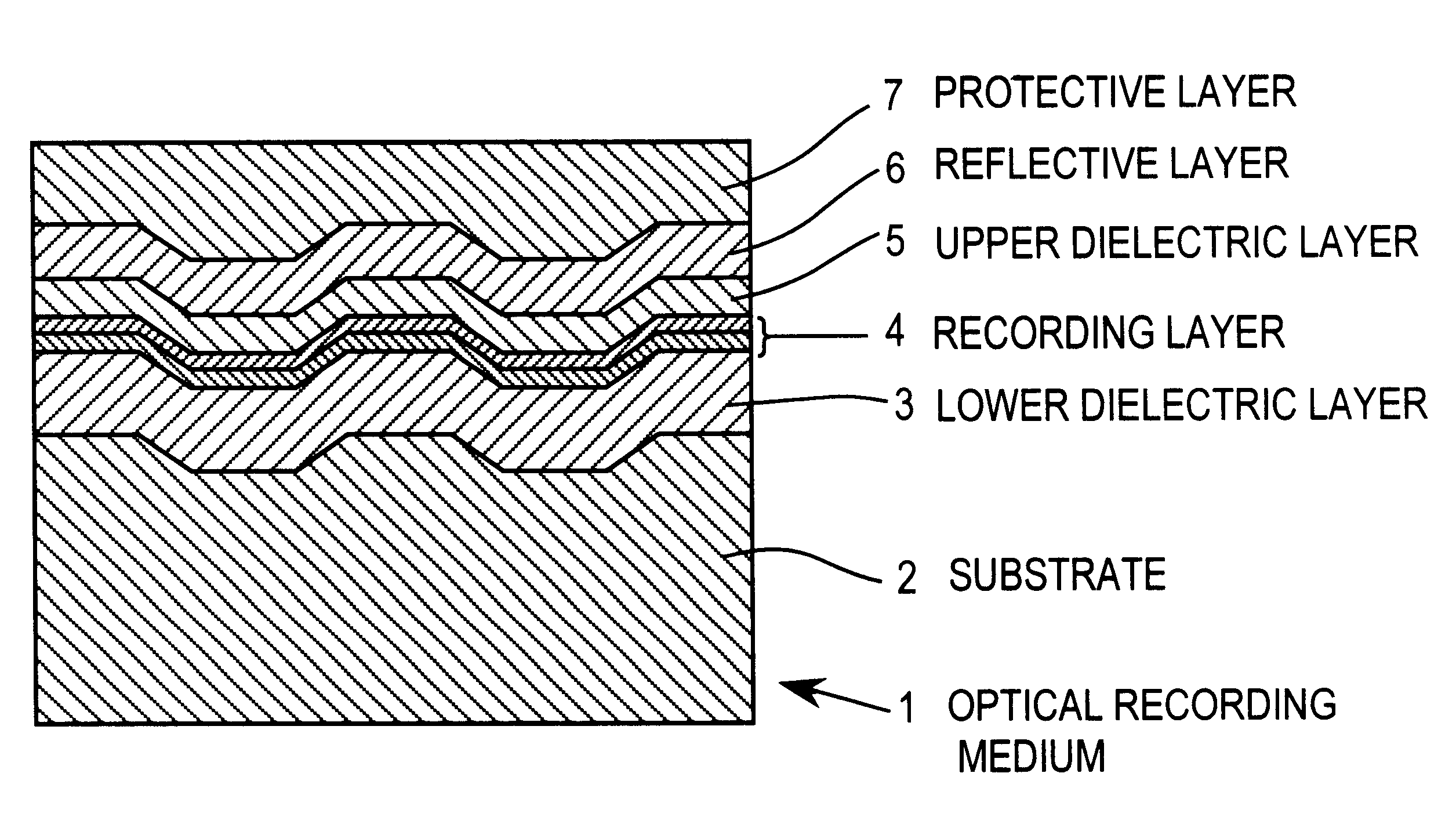
An optical recording disc as shown in FIG. 1 was prepared by injection molding polycarbonate into a disc shaped substrate 2 having a diameter of 120 mm and a thickness of 0.6 mm. A groove was formed in one major surface of the substrate simultaneous with injection molding. The groove had a width of 0.74 .mu.m, a depth of 650 .ANG., and a pitch of 1.48 .mu.m. On the grooved surface of the substrate, there were formed a lower dielectric layer 3, a recording layer 4, an upper dielectric layer 5, a reflective layer 6, and a protective layer 7.

The lower dielectric layer 3 was formed by sputtering a target of ZnS and SiO.sub.2. The value of SiO.sub.2 / (ZnS+SiO.sub.2) was 15 mol %. The lower dielectric layer had a refractive index of 2.33 at wavelength 780 nm and a thickness of 2,000 .ANG..

Next, a vacuum chamber of a sputtering apparatus was evacuated to a vacuum of 0.04.times.10.sup.-2 Pa and then charged with argon gas to a pr...

example 2

In--Ag--Te--Sb System (reactive thin film.fwdarw.Sb thin film)

A sample 2 was prepared by the same procedure as sample 1A in Example 1 except that formation of the reactive thin film was followed by formation of the antimony thin film. The ultimate gas pressure of the vacuum chamber in the recording layer forming step was the same as in Example 1. Sample 2 had a reflectance of 13%. Electron beam diffractometry analysis showed that the antimony thin film was crystalline while the reactive thin film was amorphous.

Sample 2 was subjected to mixing of the antimony thin film and the reactive thin film as in sample 1A. After the laser beam irradiation, the reflectance decreased to 10% as in sample 1A, indicating full intermixing.

Sample 2 was examined for record / erase characteristics as in sample 1A. The reflectance after recording and the C / N of a 7T (249.48 ns) signal were the same as in sample 1A. Like sample 1A, sample 2 showed a stable rate of erasure of -30 dB from the 1st overwriting ...

example 3

In--Ag--Te--Sb System (V added)

A sample 3 was prepared by the same procedure as sample 1A in Example 1 except that the composition of the antimony thin film was changed to Sb.sub.99 V.sub.1. The ultimate gas pressure of the vacuum chamber in the recording layer forming step was the same as in Example 1. Sample 3 had a reflectance of 15%. Electron beam diffractometry analysis showed that the antimony base thin film was crystalline.

Sample 3 was subjected to mixing of the antimony base thin film and the reactive thin film as in sample 1A. After the laser beam irradiation, the reflectance decreased to 13%.

Next, sample 3 was examined for record / erase characteristics as in sample 1A except that the recording power was slightly increased to 12 mW. Sample 3 had a reflectance of 20% in the crystalline region where the erasing power was applied, which was equal to sample 1A, and 6% in the amorphous region or the record mark, which was lower than sample 1A. The C / N of a 7T (249.48 ns) signal w...


PUM

PropertyMeasurementUnit
thicknessaaaaaaaaaa
linear velocityaaaaaaaaaa
diameteraaaaaaaaaa

Abstract

A phase change optical recording medium has on a substrate a recording layer consisting essentially of a Sb base thin film and a reactive thin film. The Sb base thin film is formed by depositing a Sb base material containing at least 95 at % of Sb to a thickness of 70-150 Å. The reactive thin film is formed of a material which forms a phase change recording material when mixed with Sb. The reactive thin film is typically formed of an In-Ag-Te or Ge-Te material. Stable write / read characteristics are accomplished at the first overwriting, initializing operation is eliminated, and rewriting is impossible at the same linear velocity as recording.

Description

1. Field of the InventionThis invention relates to a phase change optical recording medium and a method for preparing the same.2. Prior ArtHighlight is recently focused on optical recording media capable of recording information at a high density and erasing the recorded information for overwriting. One typical rewritable (or erasable) optical recording medium is of the phase change type wherein a laser beam is directed to the recording layer to change its crystallographic state whereupon a change of reflectance by the crystallographic change is detected. Optical recording media of the phase change type are of great interest since they can be overwritten by modulating the intensity of a single light beam and the optical system of the drive unit used for their operation is simple as compared with magneto-optical recording media.Most optical recording media of the phase change type used Ge-Te systems which provide a substantial difference in reflectance between crystalline and amorpho...

Claims


Application Information

Patent Timeline
Patent Type & Authority Patents(United States)
IPC IPC(8): G11B7/243G11B7/24G11B7/26G11B7/257B60L11/18H02J7/00H02J7/14
CPCB60L11/1809G11B7/243G11B7/257G11B7/26G11B7/266H02J7/0011H02J7/0063H02J7/14Y10T428/21G11B7/2595G11B2007/24308G11B2007/2431G11B2007/24312G11B2007/24314G11B2007/24316Y02T10/7005Y02T10/725Y02T90/127Y02T90/14Y10S430/146B60L2210/20Y02T10/7072B60L53/00Y02T10/72Y02T10/70H02J7/00Y02T90/12
Inventor TOMINAGA, JUNJIKURIBAYASHI, ISAMUTAKAHASHI, MAKOTOKIKUKAWA, TAKASHI
Owner TDK CORPARATION
Why Eureka
Try Eureka