Joint Design For Large SLS Details

a technology of sls details and joint design, applied in the field of tooling systems and processes, can solve the problems of inefficiency of physical master models, cost of master models, design, modeling and surfacing, etc., and achieve the effect of increasing the versatility of sinter systems and reducing costs and cycle tim

Inactive Publication Date: 2005-12-22
THE BOEING CO
View PDF9 Cites 59 Cited by
  • Summary
  • Abstract
  • Description
  • Claims
  • Application Information

AI Technical Summary

Benefits of technology

[0018] One advantage of the present invention is that use of Selective Laser Sintering can significantly reduce costs and cycle time associated with the tool fabrication process. An additional advantage is that tool features can be “grown” as represented by the three-dimensional computer model, thus eliminating the requirement for a master model or facility detail. The subsequent maintenance or storage of the master / facility is thereby also eliminated.
[0019] Still another advantage of the present invention is that the model remains the master definition of the tool, therefore root cause analysis or detail replacement may be done directly from the model definition. Secondary fabrication operations are further eliminated where features are “grown” per the three-dimensional solid model definition.
[0020] A further advantage is that tools larger than may be sintered by the sinter system may be sintered as individual sections and later coupled together, thereby increasing versatility of sinter systems.
[0021] Additional advantages and features of the present invention will become apparent from the description that follows, and may be realized by means of the instrumentalities and combinations particularly pointed out in the appended claims, taken in conjunction with the accompanying drawings.

Problems solved by technology

Master models are costly in that they require design, modeling and surfacing, programming, machine time, hand work, secondary fabrication operations, and inspection prior to use in tool fabrication.
In summary, although used for years, physical master models have inherent inefficiencies, including: they are costly and difficult to create, use, and maintain; there is a constant risk of damage or loss of the master model; and large master models are difficult and costly to store.
Selective Laser Sintering has, however, not been generally available for tool manufacture because of SLS part size limitations, lack if robustness of SLS objects, and inherent limitations in the SLS process.
The disadvantages associated with current tool manufacturing systems have made it apparent that a new and improved tooling system is needed.

Method used


Image

  • Joint Design For Large SLS Details
  • Joint Design For Large SLS Details
  • Joint Design For Large SLS Details

Examples


Embodiment Construction

[0029] The present invention is illustrated with respect to a sintering system particularly suited to the aerospace field. The present invention is, however, applicable to various other uses that may require tooling or parts manufacture, as will be understood by one skilled in the art.

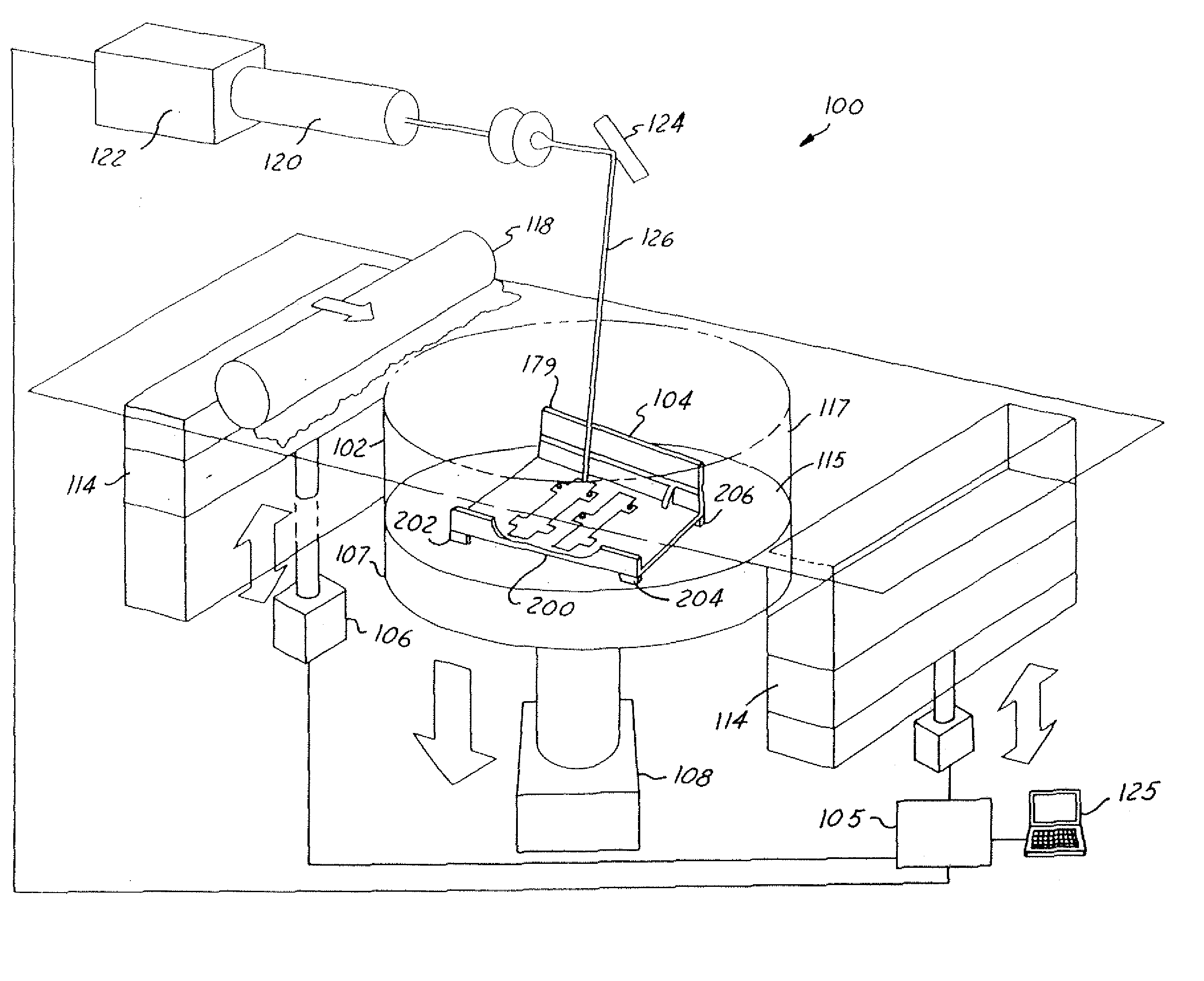
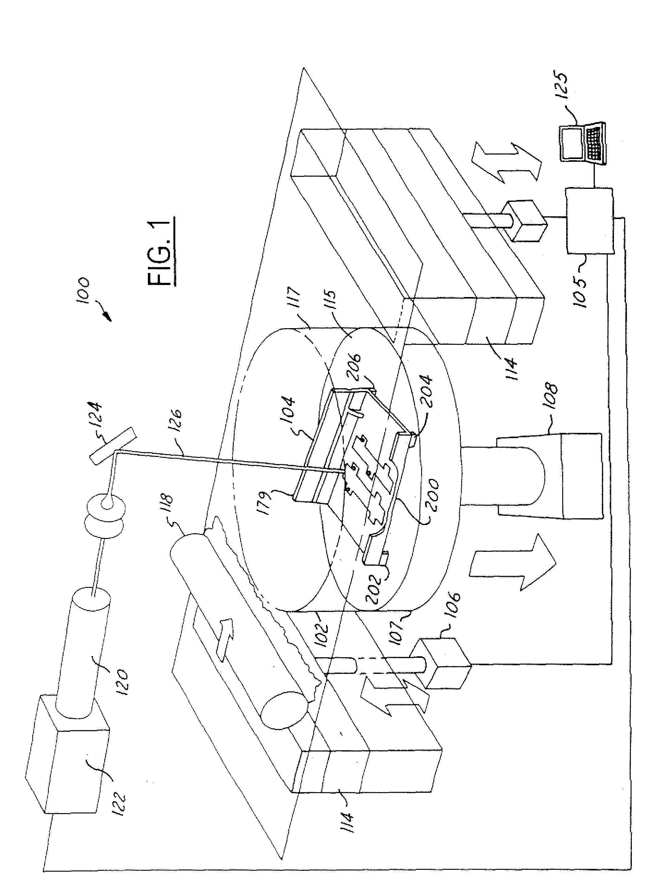
[0030]FIG. 1 illustrates a selective laser sintering system 100 having a chamber 102 (the front doors and top of chamber 102 not shown in FIG. 1, for purposes of clarity). The chamber 102 maintains the appropriate temperature and atmospheric composition (typically an inert atmosphere such as nitrogen) for the fabrication of a tool section 104. The system 100 typically operates in response to signals from a controller 105 controlling, for example, motors 106 and 108, pistons 114 and 107, roller 118, laser 120, and mirrors 124, all of which are discussed below. The controller 105 is typically controlled by a computer 125 or processor running, for example, a computer-aided design program (CAD) defining a...


PUM

PropertyMeasurementUnit
areaaaaaaaaaaa
thicknessaaaaaaaaaa
areasaaaaaaaaaa

Abstract

A system for manufacturing a tool within a laser sintering system includes a chamber enclosing a sinter material. The laser sintering system grows or sinters the tool from the sinter material in response to signals from a controller, which generates the signals as a function of a predetermined tool design. The predetermined tool design includes several sections that are grown separately and are later coupled together.

Description

FEDERAL RESEARCH STATEMENT [0001] [Federal Research Statement Paragraph]This invention was made with government support on contract N00019-01-C-0012. The Government has certain rights in this invention.BACKGROUND OF INVENTION [0002] The present invention relates generally to tooling systems and processes and is more specifically related to the fabrication of tools through selective laser sintering. [0003] Traditional fabrication methods for tools having areas of contour have included fiberglass lay-ups on numerically controlled machined master models or facility details. [0004] A manufacturing master model tool, or “master model”, is a three-dimensional representation of a part or assembly. The master model controls physical features and shapes during the manufacture or “build” of assembly tools, thereby ensuring that parts and assemblies created using the master model fit together. [0005] Traditional tool fabrication methods rely on a physical master model. These master models may ...

Claims


Application Information

Patent Timeline
Patent Type & Authority Applications(United States)
IPC IPC(8): B22F3/105B22F7/06B29C35/08B29C41/02B29C67/00
CPCB22F3/1055B22F7/062B22F2005/002B22F2998/00Y10T29/49948G05B2219/49018B29C67/0077B22F2003/1056B22F2203/01B29C64/153Y02P10/25B22F10/28B22F12/20B22F12/49B22F12/63B22F10/366B22F12/55
Inventor MACKE, JOHN G. JR.BUCHHEIT, JACK G.SAMSON, NANCY
Owner THE BOEING CO
Why Eureka
Try Eureka