Laser welding method and laser welding device

a laser welding and laser welding technology, applied in metal working devices, manufacturing tools, capacitors, etc., can solve the problems of increasing cost and cycle time, unable to stabilize the molten state, etc., and achieve sufficient laser energy absorption time, accurate timing determination, and stab welding operation

Inactive Publication Date: 2018-03-22
HONDA MOTOR CO LTD
View PDF6 Cites 3 Cited by
  • Summary
  • Abstract
  • Description
  • Claims
  • Application Information

AI Technical Summary

Benefits of technology

[0018]In this way, by the utilization of the visible light from the plume (metal vapor) in which the produced amount is increased as energy absorption proceeds, it is possible to accurately determine timing at which the absorption of the energy is started in the metal members. The timing at which laser energy absorption is started in the metal members is reflected on the control of the application, and thus the molten state which is varied depending on the metal members to be welded can be made uniform. For example, even when the metal members such as copper whose reflectance is high are the targets to be welded, since it is possible to acquire a sufficient laser energy absorption time necessary for the metal members, it is possible to stably perform a welding operation without use of a large capacity laser oscillator and performing oxidization processing on the surface of the electrical conductors, with the result that it is possible to reduce the cost and the cycle time.
[0019]According to the present invention, it is possible to provide a laser welding method and a laser welding device which can stably and efficiently supply a high-quality product by reducing a variation in laser energy absorption time.

Problems solved by technology

As shown in FIGS. 4A to 4D, in a case where laser welding is managed by time, even when the laser application time is the same, due to variations in the surface shape, the surface state and the like of the metal members, laser energy absorption times (absorption start timing) are varied for each of works (metal members), with the result that the molten state may not be stabilized.
The use of a large capacity laser transmitter or preprocessing or the like such as for oxidizing the surface of a work causes increases in cost and cycle time.

Method used


Image

  • Laser welding method and laser welding device
  • Laser welding method and laser welding device
  • Laser welding method and laser welding device

Examples


Embodiment Construction

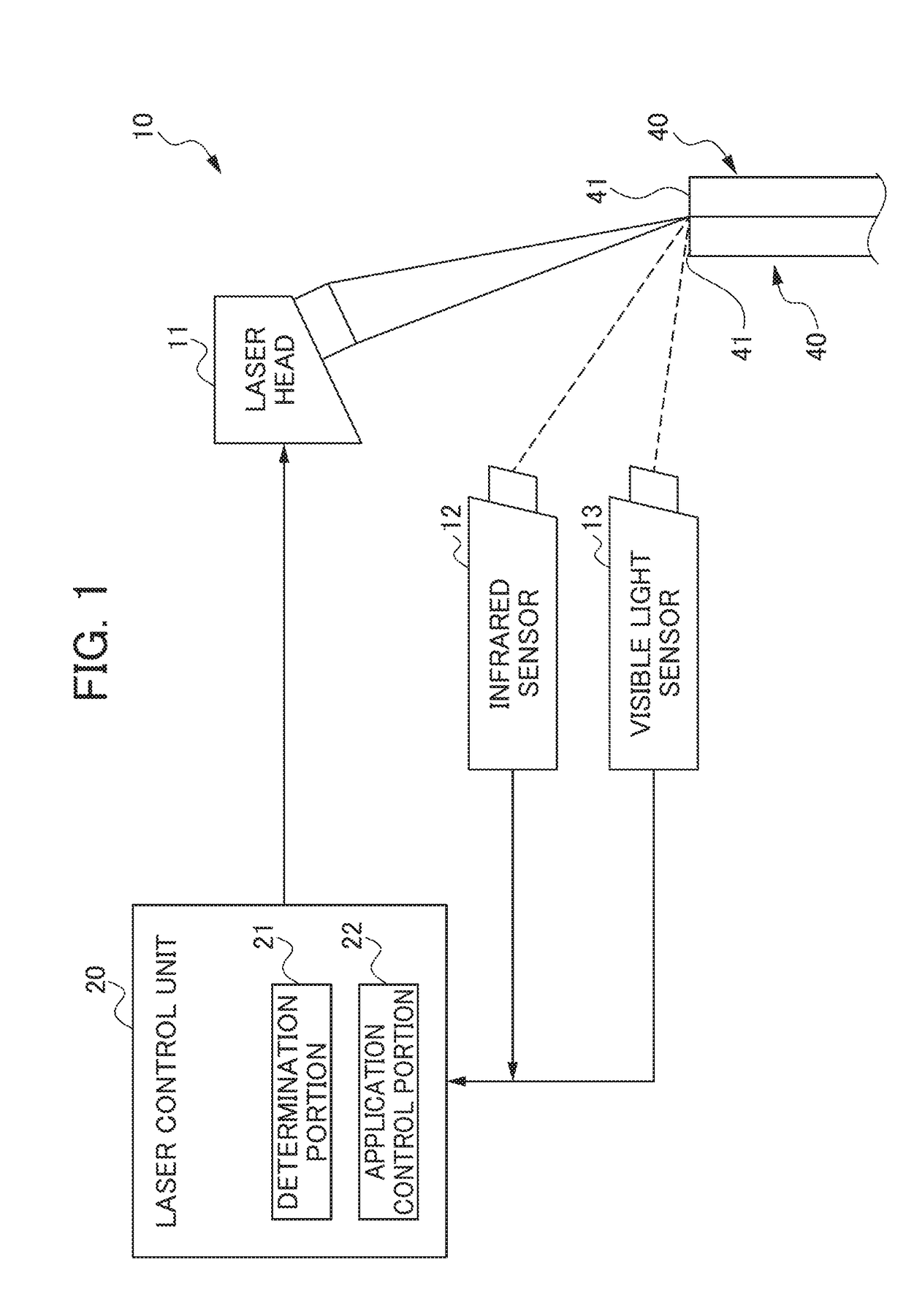
[0030]A preferred embodiment of the present invention will be described below with reference to drawings. FIG. 1 is a diagram schematically showing the unit configuration of a laser welding device 1 according to an embodiment of the present invention. The laser welding device 1 of the present embodiment performs a laser welding method of joining at least two electrical conductors 40 by laser welding.

[0031]As shown in FIG. 1, the laser welding device 10 includes a laser head 11 which applies a laser (laser light) to the electrical conductors 40, an infrared sensor (light detection portion) 12 which detects infrared light, a visible light sensor (light detection portion) 13 which detects visible light and a laser control unit 20 which controls individual portions of the laser welding device 10.

[0032]The laser head 11 is a laser application portion which applies an infrared laser to a work to be welded. The laser output from a laser oscillator (unillustrated) is applied through the las...


PUM

PropertyMeasurementUnit
energy absorptionaaaaaaaaaa
energy absorption timeaaaaaaaaaa
energy absorption timesaaaaaaaaaa

Abstract

The laser welding method includes: a step of applying, with a laser head, a laser to a joint part of electrical conductors serving as metal members to be welded and detecting, with an infrared sensor, reflected light of the laser from the joint part or detecting, with a visible light sensor, light emitted from metal vapor; and a step of comparing the detection values of the infrared sensor and the visible light sensor and setting values respectively so as to determine whether or not energy absorption is started in the electrical conductors and adjusting the control of the application of the laser based on timing at which the energy absorption is determined to be started.

Description

[0001]This application is based on and claims the benefit of priority from Japanese Patent Application No. 2016-181690, filed on 16 Sep. 2016, the content of which is incorporated herein by reference.BACKGROUND OF THE INVENTIONField of the Invention[0002]The present invention relates to a laser welding method and a laser welding device with which a metal member is joined by laser welding.Related Art[0003]Conventionally, a technology is known in which a metal member is joined by laser welding. An example of a document which discloses this type of technology is patent document 1. Patent document 1 discloses a method of manufacturing a rotary electric machine by joining, through laser welding, tip end portions of a plurality of electrical conductors one another which are inserted through individual slots provided in a stator core and which are protruded from the slots. It is known that copper used as this type of electrical conductor has a low laser absorption rate, and in order to sho...

Claims


Application Information

Patent Timeline
Patent Type & Authority Applications(United States)
IPC IPC(8): B23K26/32B23K26/70B23K31/12
CPCB23K26/32B23K31/125B23K26/705B23K26/21B23K26/702B23K26/032B23K26/22B23K2101/38
Inventor YAJIMA, SHIGEO
Owner HONDA MOTOR CO LTD
Why Eureka
Try Eureka