Composite Consumables for a Plasma Arc Torch

a plasma arc torch and consumable technology, applied in the direction of manufacturing tools, contact member manufacturing, solventing apparatus, etc., can solve the problems of increasing waste, large amount of material waste, and certain new designs of consumables, including consumables with elongated dimensions, to reduce cost and machine time, and reduce material waste

Active Publication Date: 2015-02-12
HYPERTHERM INC
View PDF9 Cites 10 Cited by
  • Summary
  • Abstract
  • Description
  • Claims
  • Application Information

AI Technical Summary

Benefits of technology

[0005]It is an objective of the present invention to provide methods for manufacturing consumables to reduce cost and machine time. It is another objective of the invention to provide at least one composite consumable made from separate bar stocks, sources, etc. to reduce material waste during manufacturing.

Problems solved by technology

Each consumable for a plasma arc torch is usually made from a single piece of bar stock, which can produce a large amount of material waste during the machining process if the consumable has varying diameters / cross-sections, thus requiring the bar stock to have a diameter of at least the largest diameter / cross-section of the consumable in many cases.
In addition, certain new designs of consumables, including consumables with elongated dimensions, produce an increasing amount of waste if manufactured from a single piece of bar stock, in addition to being time consuming to make.

Method used


Image

  • Composite Consumables for a Plasma Arc Torch
  • Composite Consumables for a Plasma Arc Torch
  • Composite Consumables for a Plasma Arc Torch

Examples


Embodiment Construction

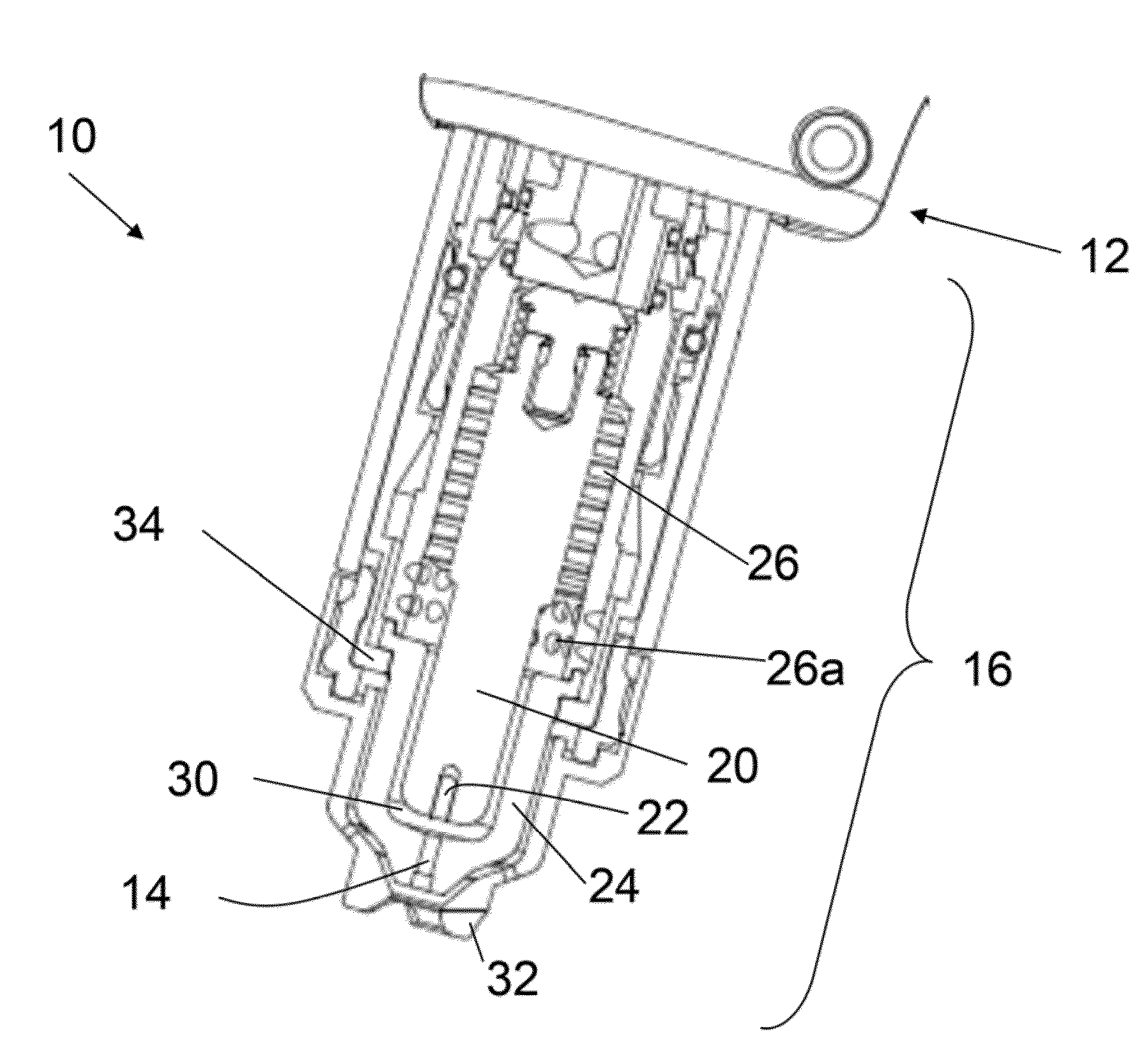
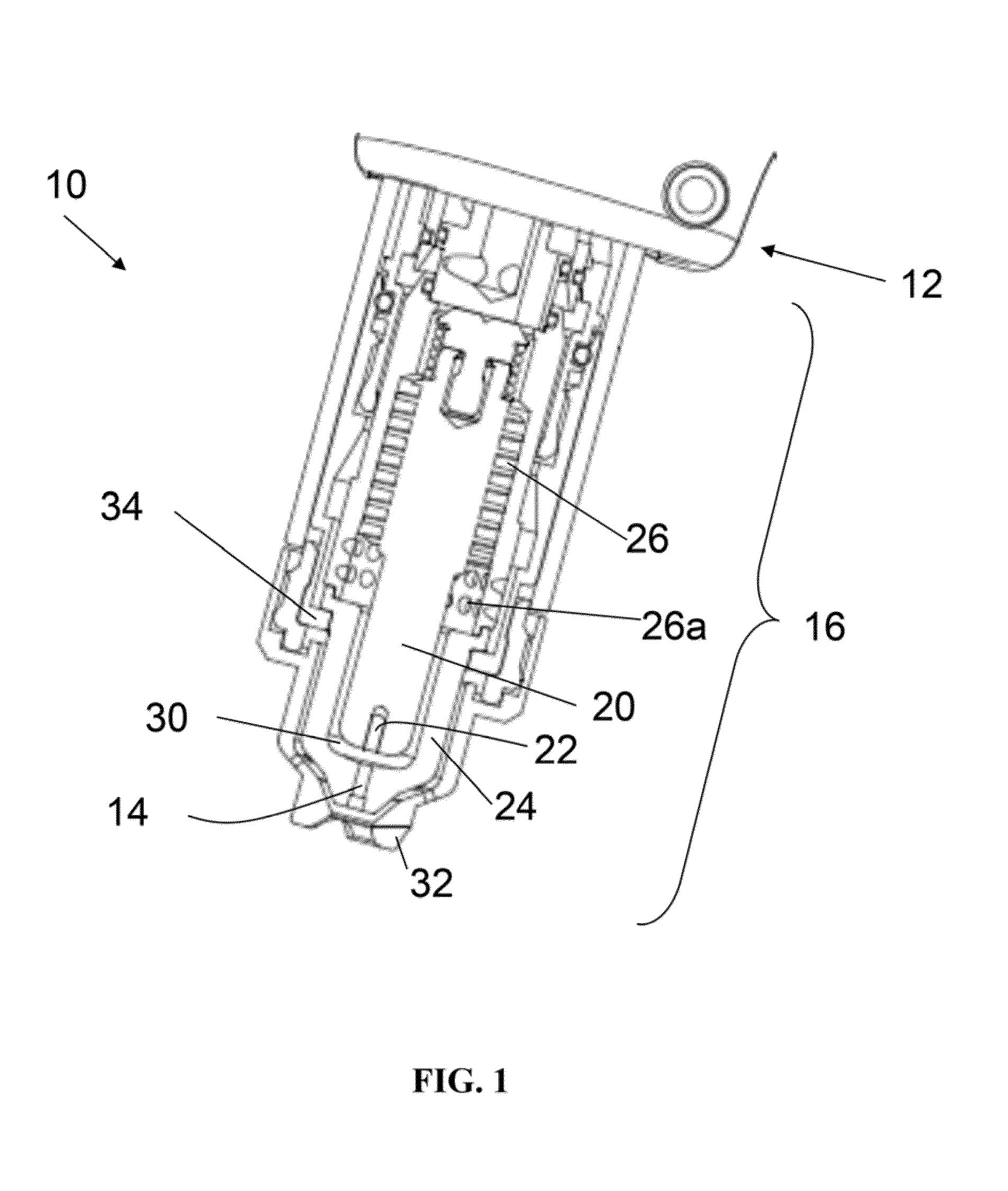
[0055]FIG. 1 shows an exemplary plasma arc torch 10 of the present invention. The torch 10 has a body 12, which is typically cylindrical with an exit orifice 14. A plasma arc, such as an ionized gas jet, passes through the exit orifice 14 and is positioned relative to a workpiece (not shown) to be cut. In a transferred arc mode, the torch 10 can pierce, cut or mark the workpiece, which can be made of a metal or another material.

[0056]The torch body 12 supports an electrode 20. An emissive insert 22 (i.e., emitter) can be disposed in the lower end of the electrode 20 so that an emission surface is exposed. The insert 22 can be made of hafnium or other materials that possess suitable physical characteristics, including corrosion resistance and a high thermionic emissivity. The torch body 12 also supports a nozzle 24, which is spaced from the electrode 20 and defines, in relation to the electrode 20, a plasma chamber 30. The nozzle 24 includes a central orifice defining the exit orific...


PUM

PropertyMeasurementUnit
densityaaaaaaaaaa
densityaaaaaaaaaa
densityaaaaaaaaaa

Abstract

An electrode is provided for use in a plasma arc torch. The electrode includes a body having an elongated forward portion and a ring-shaped aft portion. The forward portion is configured to provide an electrically conductive path from the distal end to the proximal end. The forward portion comprises a first conductive material. The ring-shaped aft portion, defining a hollow center, is configured to substantially surround a portion of the forward portion when the forward portion is located inside of the hollow center. The aft portion includes a pneumatic reaction region for receiving a biasing flow of a pressurized gas. The aft portion comprises a second material. In some embodiments, the first conductive material is the same as the second material.

Description

CROSS REFERENCE TO RELATED APPLICATIONS[0001]This application is a continuation-in-part of U.S. Ser. No. 13 / 570,526, filed Aug. 9, 2012, which is a continuation-in-part of U.S. Ser. No. 13 / 553,273, filed Jul. 19, 2012. This application is a continuation-in-part of U.S. Ser. No. 13 / 229,105 (the '105 application), filed Sep. 9, 2011, which is a continuation-in-part of U.S. patent application Ser. No. 12 / 878,512, filed Sep. 9, 2010, now U.S. Pat. No. 8,624,150. The '105 application is also a continuation-in-part of U.S. patent application Ser. No. 13 / 169,534, filed Jun. 27, 2011, now U.S. Pat. No. 8,153,927, which is a continuation of U.S. patent application Ser. No. 11 / 611,625, filed Dec. 15, 2006, now U.S. Pat. No. 7,989,727, which claims benefit of and priority to U.S. Provisional Patent Application No. 60 / 825,453, filed Sep. 13, 2006. The '105 application is a continuation-in-part of U.S. patent application Ser. No. 12 / 032,630, filed Feb. 15, 2008, now U.S. Pat. No. 8,089,025, whic...

Claims


Application Information

Patent Timeline
Patent Type & Authority Applications(United States)
IPC IPC(8): B23K35/02B23K10/00
CPCB23K10/00B23K35/0216H05H1/34Y10T29/49117Y10T29/49204H05H1/3421H05H1/3442
Inventor DARROW, CLIFFORD GLENNCHEN, CAREYSANDERS, NICHOLAS A.
Owner HYPERTHERM INC
Why Eureka
Try Eureka