Triaxial antenna coil

a triaxial antenna and coil technology, applied in the direction of antennas, antenna details, polarised antenna unit combinations, etc., can solve the problems of increasing the number of necessary operations, complex operations, and sometimes snapping of winding terminals, so as to prevent wire snapping, reduce the number of operations, and eliminate operations

Active Publication Date: 2006-05-09
MURATA MFG CO LTD
View PDF5 Cites 56 Cited by
  • Summary
  • Abstract
  • Description
  • Claims
  • Application Information

AI Technical Summary

Benefits of technology

[0008]The present invention has been realized in order to solve the problems of conventional antenna coils such as the above, and aims to provide a triaxial antenna coil that prevents snapping, increases productivity, is resilient against dropping, and suitable for being made small and light.
[0010]According to the triaxial antenna coil of this invention, a flat core has winding grooves in three intersecting axial directions, and is fixed to an insulating resin base, that has a terminal connector for external connectors and windings. Consequently, in a winding process, an operation of binding the windings and post-winding winding terminals to the terminal connectors can be performed in a single series of operations. This enables other subsequent winding operations to be performed without considering the winding terminals that were wound earlier, and in addition, eliminates operations that may result in snapped wires, thereby increasing productivity. Furthermore, by arranging the plurality of external connectors at approximately equal intervals around the outer periphery of the side faces of the base, the triaxial antenna coil is made more resilient against dropping when mounted, and against peeling of electrodes or the like.
[0011]It is an object of this invention to provide a triaxial antenna coil that prevents wires from snapping, increases productivity, is resilient against dropping, and is suitable for being made small and light. The triaxial antenna coil has coils that are wound around three intersecting axes, and includes a flat core having winding grooves in three intersecting axial directions, and a base having a terminal element, that is fitted with a plurality of external connectors and terminal connectors of windings. The base is fixed to one face of the core, the coils are wound in respective winding grooves, and their terminals are electrically connected to the terminal connectors of the terminal element.

Problems solved by technology

This operation is complex, and the winding terminals sometimes snap.
In the assembly process of storing the coil 20 in the case 28, each winding terminal must be connected to an external terminal, leading to problems such as snapping and the like during binding, and increasing the number of necessary operations.
Connecting electrodes directly to the faces of a core that does not use a case results in problems of high deterioration in Q caused by the electrode faces, the electrodes peel off easily, and core loss on the electrode faces.

Method used


Image

  • Triaxial antenna coil
  • Triaxial antenna coil
  • Triaxial antenna coil

Examples


Embodiment Construction

[0017]A preferred embodiment of this invention will be explained based on FIGS. 1 to 3.

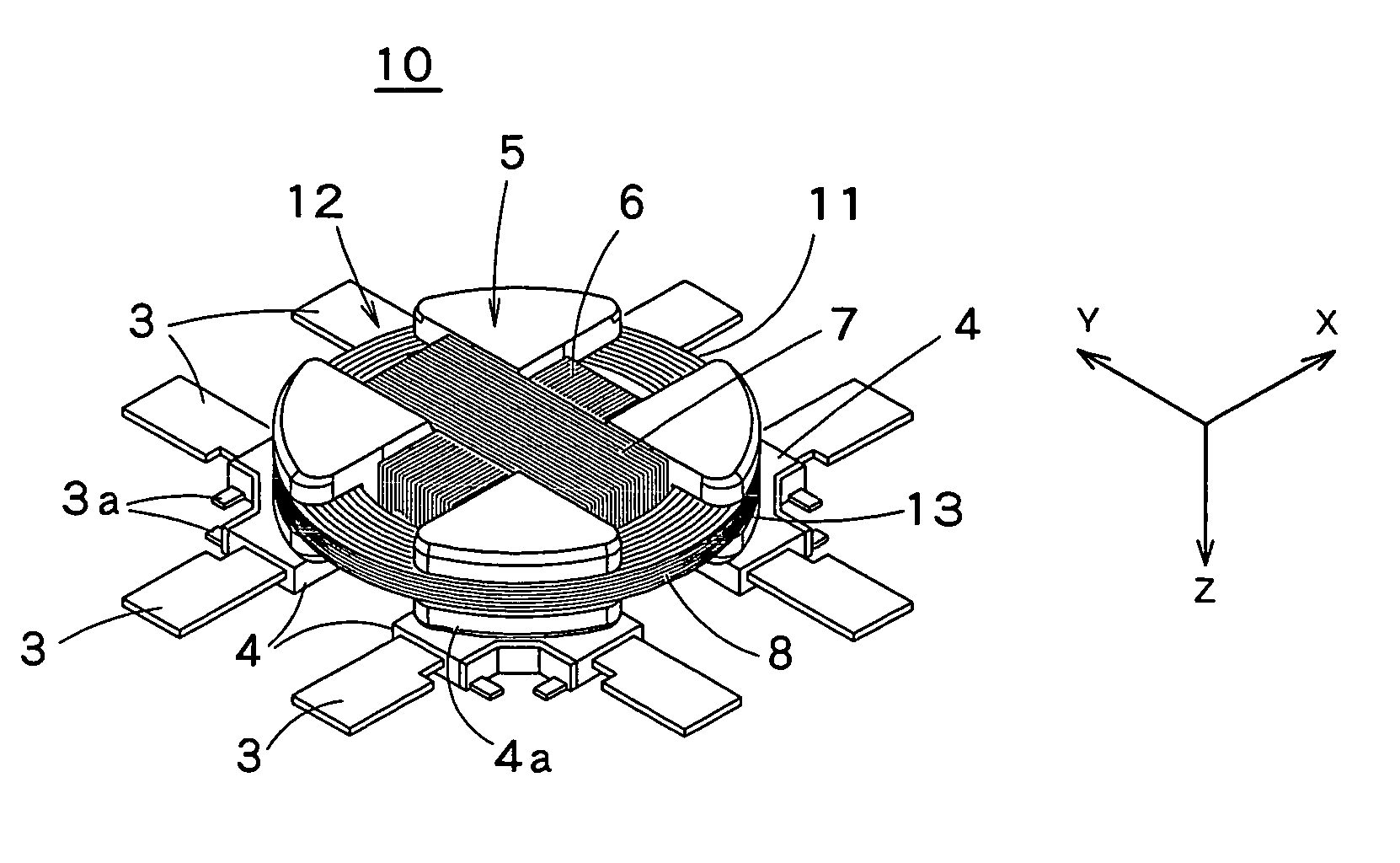
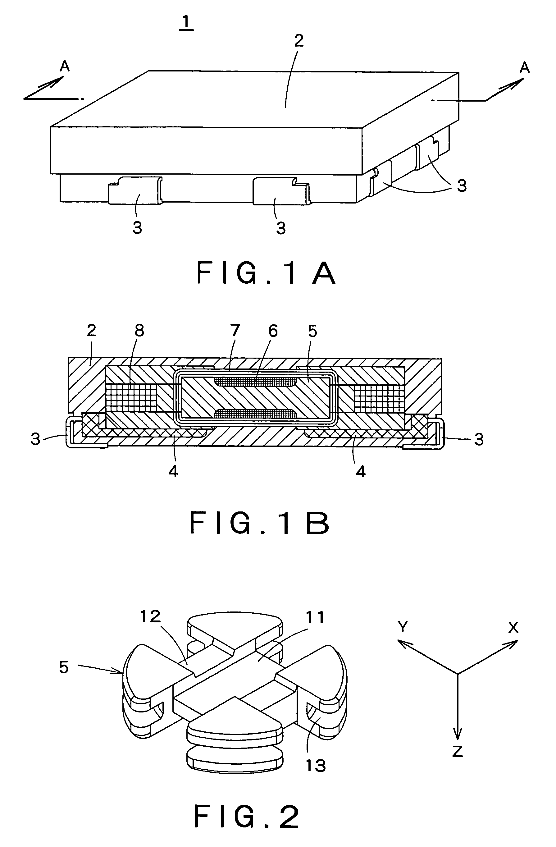
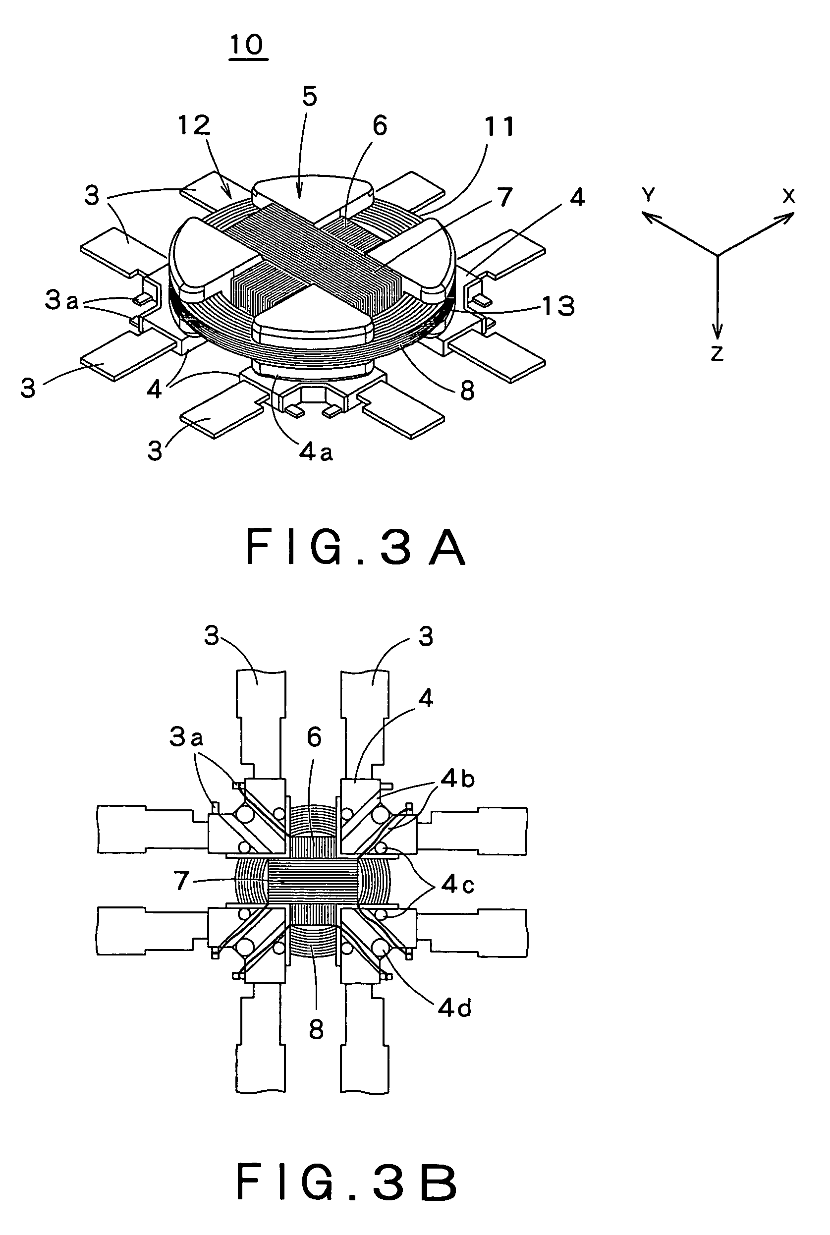
[0018]FIG. 1A is a perspective view of the triaxial antenna coil according to an embodiment of this invention, and FIG. 1B is a cross-sectional view taken along the line A—A of FIG. 1A. FIG. 2 is a perspective view of a core. FIG. 3A is a perspective view of a coil that is wound around a core, and FIG. 3B is a bottom view of the same.

[0019]As shown in FIGS. 1A and 1B, the triaxial antenna coil 1 according to the embodiment of this invention includes an outer resin 2, external terminals 3, a base 4, a core 5, a first coil 6, a second coil 7, and a third coil 8.

[0020]The core 5 is entirely covered by the outer resin 2, and the eight external terminals 3 (four opposing each other on opposite sides) are extracted from the centers of the side faces and formed along the bottom face sides, where they function as external connectors. As shown in the cross-sectional view of FIG. 1B, on the inside of the tr...


PUM

PropertyMeasurementUnit
heat-resistantaaaaaaaaaa
insulating propertiesaaaaaaaaaa
heat-aaaaaaaaaa

Abstract

A triaxial antenna coil prevents wires from snapping, increases productivity, is resilient against dropping, and is suitable for being made small and light. A triaxial antenna coil includes coils, that are wound around three intersecting winding axes, and a flat core having winding grooves in three intersecting axial directions. A base has a terminal element, that is fitted with a plurality of external connectors and terminal connectors of windings. The base is fixed to one face of the core. The coils are wound in respective winding grooves, and their terminals are connected to the terminal connectors of the terminal element.

Description

BACKGROUND OF THE INVENTION[0001]1. Field of the Invention[0002]The present invention relates to a small-scale triaxial antenna coil, that is used in a receiver or the like of a radio-controlled keyless entry system and a crime-prevention device.[0003]2. Description of the Related Art[0004]An antenna coil is used in a receiver or the like of a keyless entry system and a crime-prevention device, that are widely used in vehicles and the like. Recently, instead of a conventional antenna coil that includes a plurality of rod-like ferrite cores with windings around them for receiving waves in their respective directions, there is being used a miniaturized triaxial antenna coil that is installed in one part of a miniaturized receiving apparatus and can receive waves in all directions, as shown in FIGS. 4 and 5.[0005]FIG. 4 is a perspective view of a conventional antenna coil, and FIG. 5 is a perspective view of the coil section of FIG. 4 (Cf. Japanese Laid-Open Patent Application No. 2003...

Claims


Application Information

Patent Timeline
Patent Type & Authority Patents(United States)
IPC IPC(8): H01Q7/08H01F3/00H01Q7/06H01Q21/24
CPCH01Q21/24H01Q7/06H01F2003/005
Inventor YAGI, MASAYOSHIMURAKAMI, SHIN
Owner MURATA MFG CO LTD
Why Eureka
Try Eureka