
Modular decorative light system

a technology of decorative light and module, applied in the field of decorative light systems, can solve the problems of consuming a large amount of power, limited availability of light sets that may be utilized both indoors and out-of-doors, and therefore can be expensive to light on a regular basis, and achieves less computational capability and expense, less degree of independence, and extended control.

Inactive Publication Date: 2009-03-24
WHAM DEV HK PSHP
View PDF6 Cites 110 Cited by
  • Summary
  • Abstract
  • Description
  • Claims
  • Application Information

AI Technical Summary

Benefits of technology

"The patent describes a decorative light system that can be easily expanded and modified by adding or removing lamp modules. The modules are connected in parallel or time delay to create pre-defined light colors and sequences. The system is powered by a direct current and can be controlled by a master controller or module microprocessors. The system can be expanded using extension connectors or designated master and slave modules. The technical effects of this invention include flexibility, customization, and improved control over lighting effects."

Problems solved by technology

Currently available light sets that may be utilized both indoors and out-of-doors are limited.
There are, however, numerous disadvantages to this type of light set.
Because each bulb in a given string of lights consumes approximately 5 to 10 watts of power, a single string of 25 to 50 bulbs consumes a significant amount of power and can therefore be expensive to light on a regular basis.
Additionally, the large-bulb incandescent light sets generate appreciable amounts of heat which can lead to fire hazards.
For this reason, large-bulb incandescent light sets are not properly usable indoors.
Finally, large-bulb light sets are costly both to purchase and to maintain.
While this type of light set can be used indoors and out-of-doors and is less expensive to purchase and maintain than the large-bulb incandescent light set, there are several drawbacks associated with miniature light sets.
Lamps on miniature light sets may be connected in series and can be extremely difficult to maintain.
In some sets, a single burned-out lamp results in an open circuit that prevents operation of other lamps in the strand until the defective lamp is replaced.
In newer sets, a shunt may be present to allow current to pass to the rest of the strand even when a bulb burns out, but the shunt does not prevent malfunction of the entire strand where a bulb becomes slightly dislodged from its socket.
This may mean systematically checking each lamp on the strand, which can be both time-consuming and frustrating.
Most users are likely to conduct such a search while the strand remains plugged into the power source, thereby risking electrical shock.
Moreover, the lamps themselves are small, difficult to grasp, difficult to remove, and delicate to handle.
Consequently, time spent searching for a defective lamp and the associated risk of injury from shock or from crushing the glass portion of the lamps while removing and replacing them is burdensome at best.
Sometimes, entire light sets are often discarded even if only a single lamp is defective, making repeated purchases of conventional decorative light sets less cost effective than their price would indicate.
While this reduces potential danger from voltage as compared to the large-bulb incandescent light systems, it also means that a user must have access to an AC outlet, necessarily limiting the use of conventional light sets to certain applications where AC power is convenient.
Further, if multiple extension cords are necessary, a display can quickly become both unattractive and hazardous with respect to circuit overload and fire.
Moreover, although miniature light sets allow a user to connect multiple strands of lamps to one another to create longer strands for more extensive applications or for the convenience of avoiding multiple extension cords in a single application, a user is still constrained by high current draws that could overload the circuit and permanently damage the light set.
Another practical problem with miniature light sets is the difficulty of creating dense or intricate light displays because the lamps on miniature light sets have a fixed space, usually 4 to 6 inches or more from one another.
This often leads to problems with tangling and breakage, especially if a bulb is loose or needs replacing or if the light strands must be taken down often, such as in a seasonal or temporary applications.
A further issue with miniature light sets is the limited range of available light colors.
Even assuming that a user might be satisfied with the few lamp colors available on the market for miniature light sets, changing the color scheme on even a single strand of conventional lights is problematic, and more so for multiple strands of lights.
Again, because the lights are small, delicate, and difficult to remove and replace, a user is likely to decide against changing color schemes to avoid the extra effort required to change colors.
Although the cost of purchasing all-new replacement lamps is not necessarily prohibitive, the difficulty of finding enough replacement lamps in the desired replacement color is often difficult if not impossible.
Practically, then, a user is more likely to purchase an entire new light set when new colors are desired, but even then, the selection of available colors remains small.
Similarly, the range of flashing patterns available in miniature lighting systems is narrow.
Unfortunately, the strand will not light at all when the blinker bulb burns out.
Because most light sets only come with one flasher or two at most, any defect or damage to the flasher bulb may further limit a user's options with respect to flashing patterns.
Even in the more advanced miniature light sets run by a controller, available flashing patterns are usually preset and the selection is limited.
Finally, transitioning from structure to another, when lighting a series of structures is almost always problematic.
In the former case, a user must purchase multiple extension cords and is limited by the number of AC power outlets available.
In the latter case, a user must move from one window to the next by extending lighted portions of strands between the two windows, thus detracting from the aesthetic quality of the display.
Control protocol is another major problem.
It is difficult to provide a high level of control in most systems without knowing the size of the system.
Systems which have a variable size are almost impossible to provide with distributed control.

Method used


Image

  • Modular decorative light system
  • Modular decorative light system
  • Modular decorative light system

Examples


Embodiment Construction

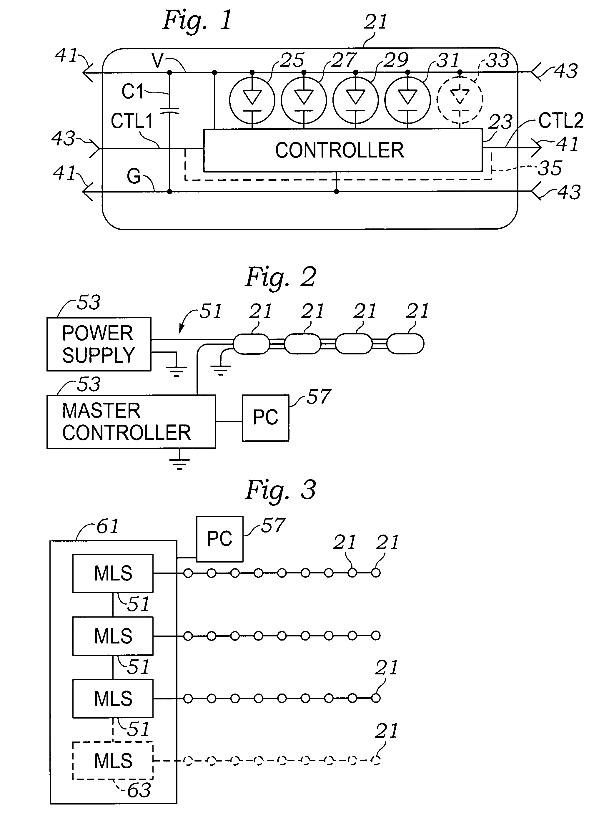
[0048]Referring to FIG. 1, a description of the modular decorative light system will be initiated with reference to a schematic diagram of a potential design which may be used for a module for the modular decorative light system. A light module 21 is intended to be a repeating unit in a system, regardless of how it is housed, connected or mechanically supported.

[0049]The light module 21 has three main conductors which extend through it. A voltage / current supply Line V which is the more positive potential voltage line, a ground line G, and a control lines CTL1 and CTL2. The voltage / current supply Line V may be a conductive line which provides positive potential direct current energy to a controller 23, and a series of LED's 25, 27, 29, 31, and 33 where LED 33 represents further LED's. The controller 23 is connected to the ground line G, and also controls the access to ground for the LED's 25, 27, 29, 31, and 33 internally.

[0050]A pair of data lines include line CTL1 as a first line t...


PUM


Abstract

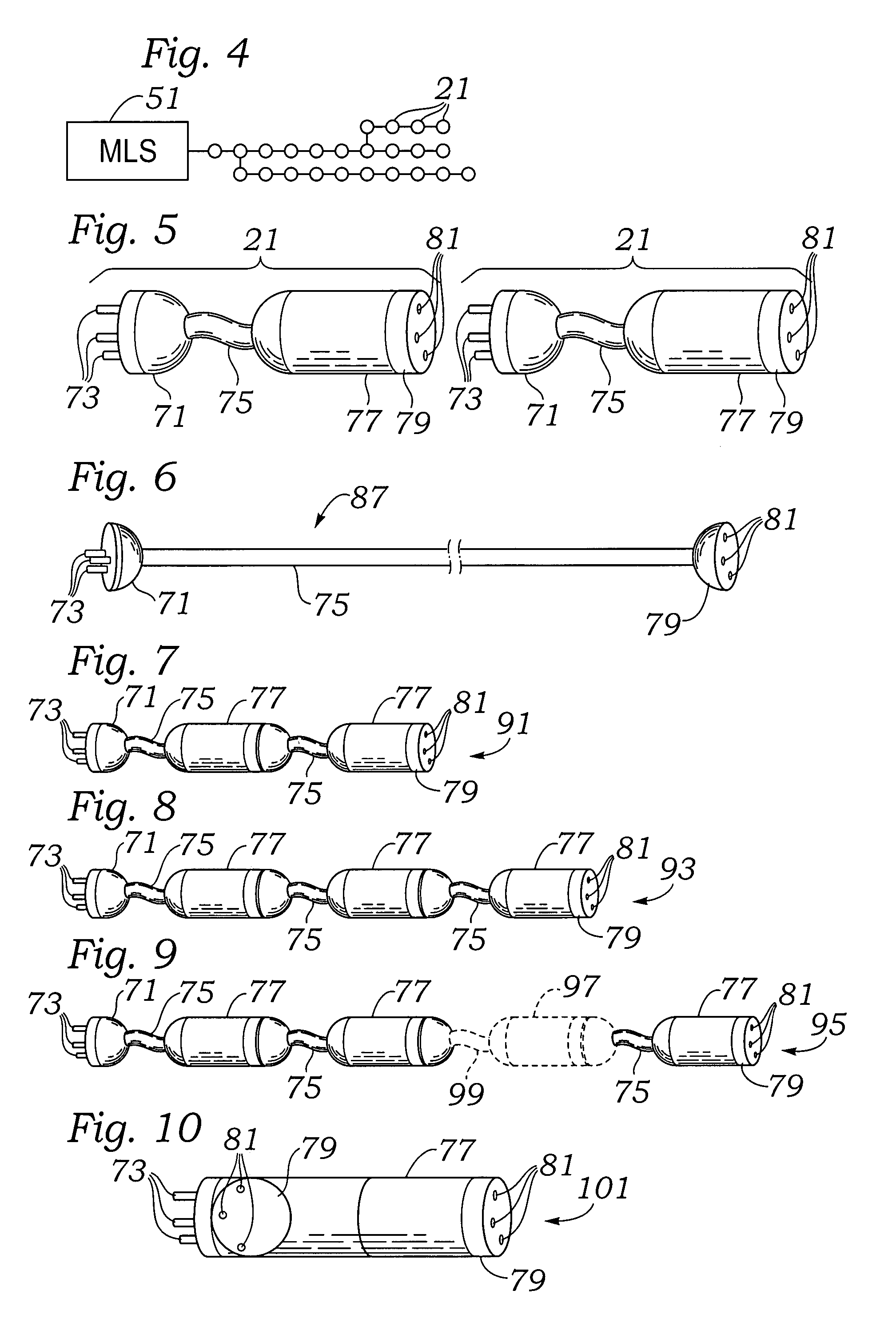
A sculptable, decorative light system includes a number of modules of differing lengths which can respond to commands either in parallel or time delay to create pre-selected light colors and sequences. Three miniature connectors are used to create a direct current fed system which has the potential to even out a current demand. Interconnectable lamp modules are provided in sets of 1, 2, 3, 4, and more lengths to create decorative light displays. Each lamp module or string of modules may include a male / plug end and a female / receptacle end.

Description

FIELD OF THE INVENTION[0001]The present invention relates to the field of decorative light systems such as those utilized for holiday decorations and those used in year-round displays frequently seen at restaurants, shops, or hotels, and more particularly to programmable decorative light systems capable of displaying a vast selection of colors and flashing patterns.BACKGROUND OF THE INVENTION[0002]Currently available light sets that may be utilized both indoors and out-of-doors are limited. For holiday lighting, one available option for outdoor lighting is a large-bulb incandescent light set. Such light sets are still available on the market and are often necessary where a user wishes to create a bright and dramatic display. One advantage of large-bulb light sets is that they are typically wired in parallel so that failure of a single bulb does not prevent the rest of the strand from lighting. There are, however, numerous disadvantages to this type of light set. Because each bulb in...

Claims


Application Information

Patent Timeline
Patent Type & Authority Patents(United States)
IPC IPC(8): F21S4/00
CPCH05B33/0842H05B37/029H05B47/155H05B47/165H05B45/20H05B45/32
Inventor WONG, MING YIU
Owner WHAM DEV HK PSHP
Learn More