Plating system for bone fixation and subsidence and method of implantation

a plating system and bone technology, applied in the field of skeletal plating systems, components thereof, and methods of implant placement, can solve the problems of adding to the cost of manufacturers, vendors, end users (hospitals), and pre-manufactured sizes that may not precisely fit all patients, and add to the cos

Active Publication Date: 2008-02-19
ABDOU M SAMY
View PDF18 Cites 67 Cited by
  • Summary
  • Abstract
  • Description
  • Claims
  • Application Information

AI Technical Summary

Benefits of technology

[0018]Extension of the fusion at a later date is easily accomplished without plate removal. An adapter is placed at either end of the plate that can couple with either a modified distraction screw or an additional bone plate. Fusion extension is started by connecting a modified distraction screw to the coupler at-the end of the plate immediately adjacent to the disc to be removed. A modular distraction screw is inserted into the adjacent vertebra and a discectomy and subsequent fusion are performed within the intervening disc space. After completion of the bone work, the modified distraction screw is removed le

Problems solved by technology

This mandates that a large number of different size plates must be made and inventoried—adding to cost for manufacturer, vendor, and end user (hospitals).
More importantly, the pre-manufactured sizes may not precisely fit all patients forcing surgeons to choose between a size too small or too large.
This not only ignores the known anatomical difference in size between bones at different levels but also fails to anticipate that a patient's unique pathology may require more extensive bony resection at one or more levels, further adding to these differences.
Thus, selection of a plate with a suitable total length may still produce improper fit at one or more levels.
Current cervical plates are not modular, and will not permit addition of one plate to another for extension of the bony fusion at a future date.
This surgical procedure necessitates re-dissection through the prior, scarred operative field and substantially increases the operative risk to the patient.
Further, since mis-alignment of the original plate along the vertical axis of the spine is common, proper implantation of the replacement plate often requires that the new bone screws be placed in different bone holes.
The empty holes that result may act as stress concentration points within the vertebral bodies, as would any empty opening or crack within a rigid structural member, and lead to bone fracture and subsequent screw/plate migration.
Since bone re-absorption at the bone/graft interface is the first phase of bone healing, fixation that is too rigid will not permit the bone fragments to settle and re-establish adequate contact after initial bone absorption.
This process is known as “stress shielding” and will lead to separation of the bony fragments and significantly reduce the likelihood of bony fusion.
Unsuccessful bon

Method used


Image

  • Plating system for bone fixation and subsidence and method of implantation
  • Plating system for bone fixation and subsidence and method of implantation
  • Plating system for bone fixation and subsidence and method of implantation

Examples


Embodiment Construction

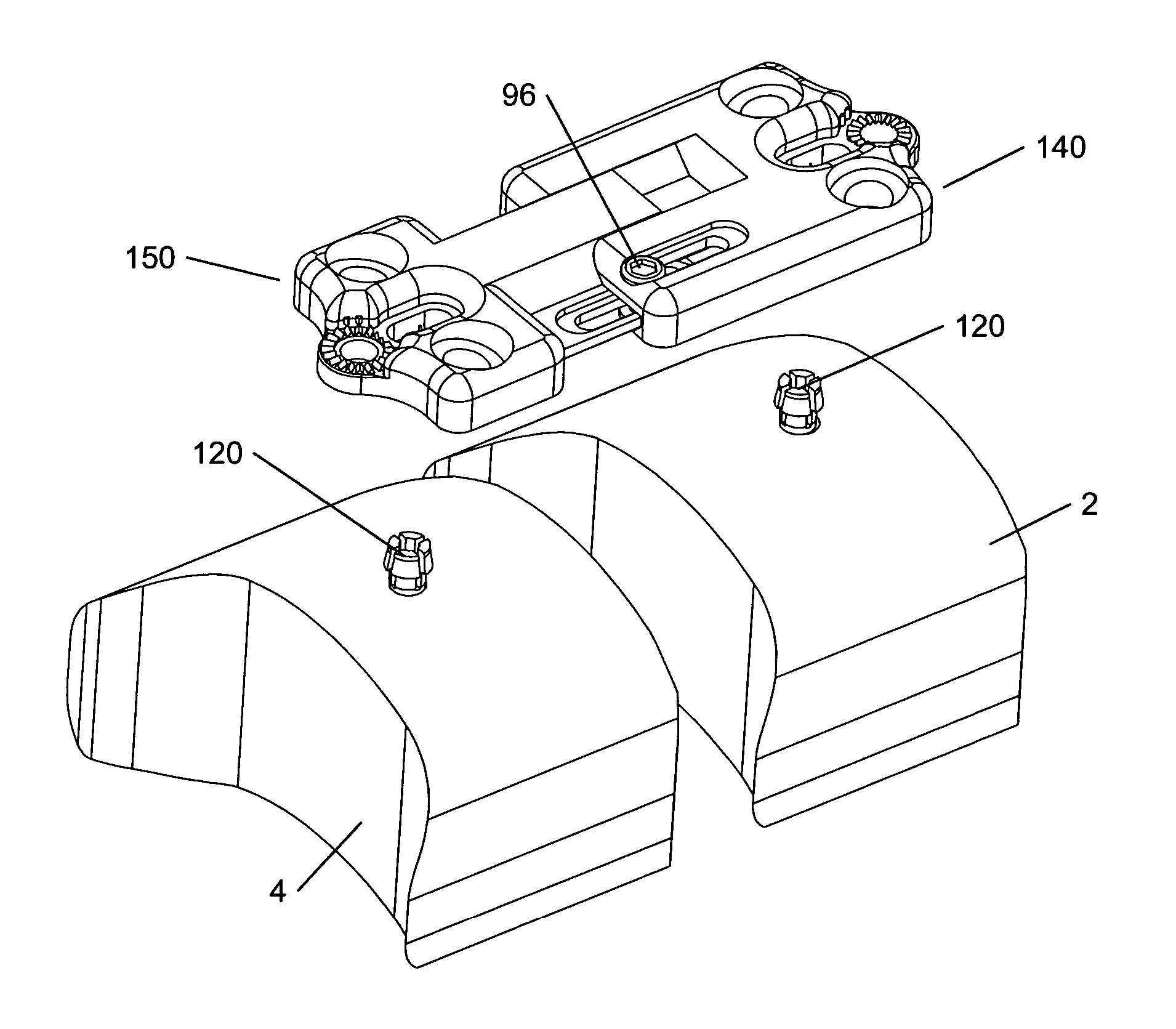
[0055]Certain embodiments as disclosed herein provide for a modular bone distraction screw and a modular bone fixation plate with an adjustable length to accommodate bone settling. For example, one plating system disclosed herein allows for compression to be set during placement of the plate and also allows subsidence of the bone while maintaining the initial compression.

[0056]After reading this description it will become apparent to one skilled in the art how to implement the invention in various alternative embodiments and alternative applications. However, although various embodiments of the present invention will be described herein, it is understood that these embodiments are presented by way of example only, and not limitation. As such, this detailed description of various alternative embodiments should not be construed to limit the scope or breadth of the present invention as set forth in the appended claims.

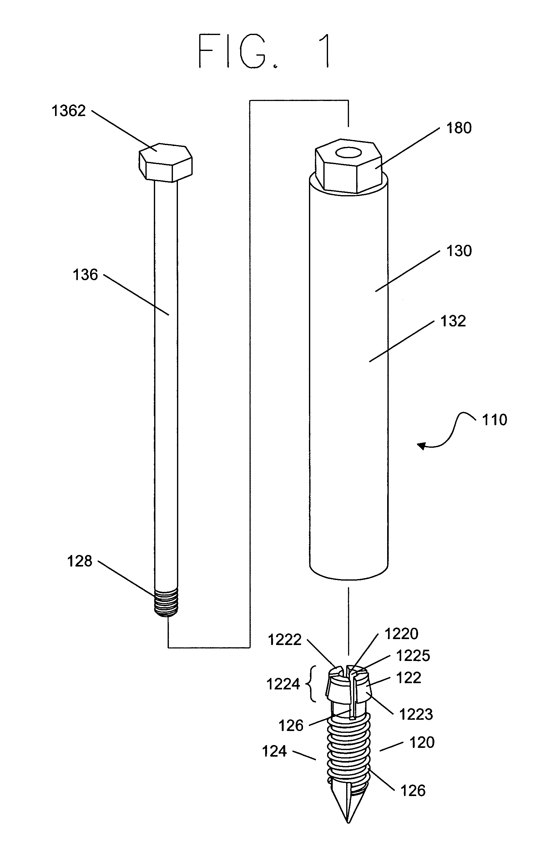
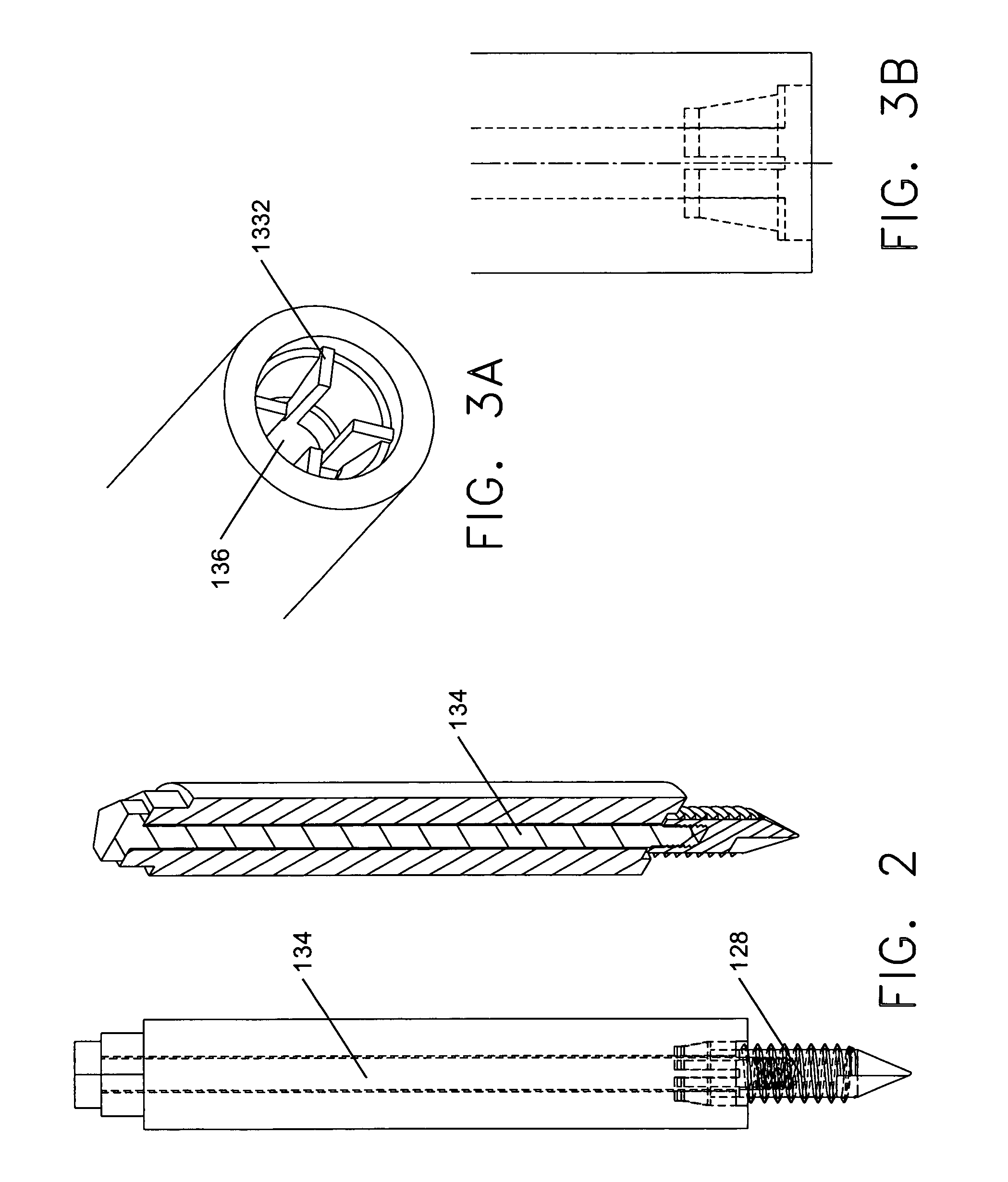
[0057]FIG. 1 shows a modular distraction screw 110, which comprises ...


PUM


Abstract

A bone plating system is provided that permits maintenance of a compression force while also accommodating bony subsidence, among other features. Methods of implantation are also provided that improve alignment and placement during implantation and avoid maneuvers that weaken the vertebral bodies. A modular distraction screw is placed during the initial stages of surgery when all relevant landmarks are still intact. After completion of the surgical bone work, a proximal end of the distraction screw is detached, leaving a protruding distal segment implanted in the centerline of the vertebral bodies above and below the newly fused disc space. A bone plate is guided into proper position relative to the upper and lower vertebra by attaching the bone plate to the protruding distal segments. The distal segments of the distraction screws are tightened onto the plate and the plate is held stationary while bone screws are placed. The bone plating system is also extendable, allowing additional bone plates to be placed and coupled with existing plate components to create a multi-level plating system. Additional bone plates may be placed contemporaneously or during a subsequent surgical procedure.

Description

RELATED APPLICATION[0001]The present application claims priority to co-pending U.S. provisional patent application Ser. No. 60 / 439,030 filed on Jan. 10, 2003, and is a continuation-in-part of co-pending U.S. patent application Ser. No. 10 / 683,325 filed on Oct. 10, 2003, each of which is incorporated herein by reference in its entirety.BACKGROUND[0002]1. Field of the Invention[0003]The present invention is directed at skeletal plating systems, components thereof, and method of implant placement. These systems are used to adjust, align and maintain the spatial relationship(s) of adjacent bones or bony fragments during healing and fusion after surgical reconstruction of skeletal segments. Such systems may be comprised of bone distraction devices, skeletal plates, bone screws and / or bone cables, bone screw-to-plate locking mechanisms, and any additional instruments needed for implant placement.[0004]2. Related Art[0005]Whether for degenerative disease, traumatic disruption, infection or...

Claims


Application Information

Patent Timeline
IPC IPC(8): A61B17/56A61BA61B17/02A61B17/58A61B17/70A61B17/80A61B17/86A61F2/44
CPCA61B17/8004A61B17/7059A61B17/8605A61B17/869A61B2017/0256
Inventor ABDOU, M. SAMY
Owner ABDOU M SAMY
Why Eureka
Try Eureka