Replaceable light emitting diode module

a light-emitting diode and module technology, applied in the field of diodes, can solve the problems of inconvenient replacement of defective or different colors

Active Publication Date: 2006-02-14
CHENG KUNG CAPITAL LLC
View PDF3 Cites 104 Cited by
  • Summary
  • Abstract
  • Description
  • Claims
  • Application Information

AI Technical Summary

Benefits of technology

[0006]An object of this invention is to replace a defective LED in a LED module easily. Another object of this invention is to replace or install a different color LED in a LED module. Still another object of this invention is to form a pattern changeable LED display panel.

Problems solved by technology

The drawback of such a structure is that it is inconvenient to replace a defective or different color LED in the module.

Method used


Image

  • Replaceable light emitting diode module
  • Replaceable light emitting diode module
  • Replaceable light emitting diode module

Examples


second embodiment

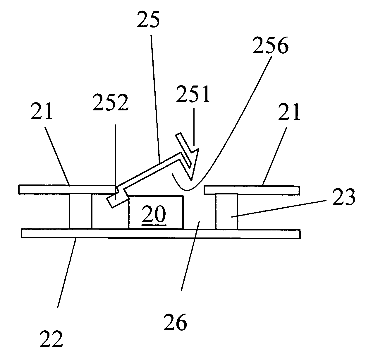
[0023]FIG. 6 shows the present invention. An array of the LED 20 and the clip 25 shown in FIG. 5 is mounted over a display panel 261. The LED modules are mounted over a common bottom plate 22 and latched between parallel rails of top metal plates 21, which is insulated from the bottom plates 22 by insulating spacers 23. The LED 20 with the clip 25 can be inserted in the space 26 uniformly or selectively to form specific patterns or characters so as to function as a commercial advertisement light board.

third embodiment

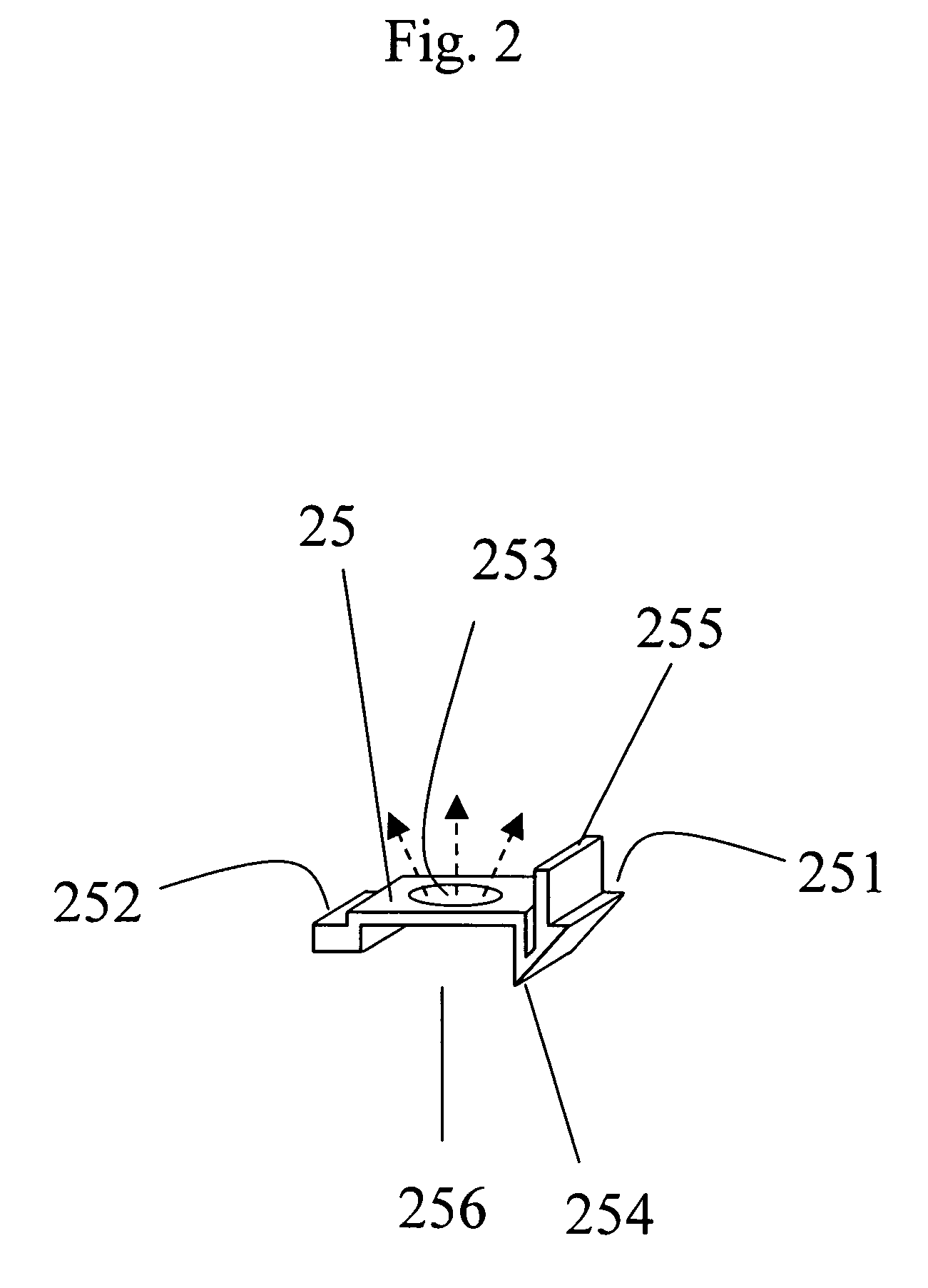
[0024]FIG. 7 shows the present invention. The clip 35 has two symmetrical flanges instead of a single flange shown in FIG. 2. Each cantilever flange has a handle 255. To latch the clip 25 for holding the LED 20 in place, the two handles are pushed toward each other for sliding the clip 25 over the LED 20. The other parts of the structure are the same as that in FIG. 4.

fourth embodiment

[0025]FIG. 8 shows the present invention. A lens 201 is mounted over the LED 20 in the structure shown in FIG. 7. The lens can focus, parallelize, or diversify the light emitted from the LED 20.


PUM


Abstract

A clip is used to clamp a LED in place in a LED module. The clip has pliable conducting cover and can be latched to the upper lead metal of the LED module. The clip can be lifted for replacing a defective or color LED. A plurality of replaceable LEDs can be mounted a common metal substrate to form a display panel, and each LED can be clamped in position with clips straddling between parallel upper lead metal for electrical coupling to the top electrodes of the LED.

Description

BACKGROUND OF THE INVENTION[0001]1. Field of the Invention[0002]This invention relates to diodes such as light emitting diodes (LED) or vertical cavity surface emitting laser diodes, particularly a replaceable module for a light emitting diode.[0003]2. Brief Description of Related Art[0004]FIG. 1 shows a prior art module for mounting a LED as disclosed in USPTO Publication No. 2004 / 0227146. A LED 10 has a top electrode 101 and a bottom electrode 102. The LED 10 is clamped between an upper metal bracket 11, which is connected to the tops electrodes 101, and a lower metal plate 12, which is connected to the bottom electrode 102. The upper metal bracket 11 and the lower metal plate 12 are locked in place by a clamp (not shown), and are used as terminals for a surface mount module.[0005]The drawback of such a structure is that it is inconvenient to replace a defective or different color LED in the module. To replace a LED, the clamp must be dismantled.SUMMARY OF THE INVENTION[0006]An ob...

Claims


Application Information

Patent Timeline
Patent Type & Authority Patents(United States)
IPC IPC(8): H01L33/00H01L23/34H01L33/48H01L33/62
CPCF21K9/00F21V19/001F21V19/004F21V19/04H01L24/72H01L33/483H01L33/62F21V19/042F21Y2101/02F21Y2101/025H01L2924/12041F21K9/20F21Y2115/30F21Y2115/10H01L2924/00
Inventor WU, JIAHN-CHANG
Owner CHENG KUNG CAPITAL LLC
Why Eureka
Try Eureka