

Method for co-channel interference cancellation in a multicarrier communication system
- Summary
- Abstract
- Description
- Claims
- Application Information
AI Technical Summary
Benefits of technology
Problems solved by technology
Method used
Image

Examples
Embodiment Construction
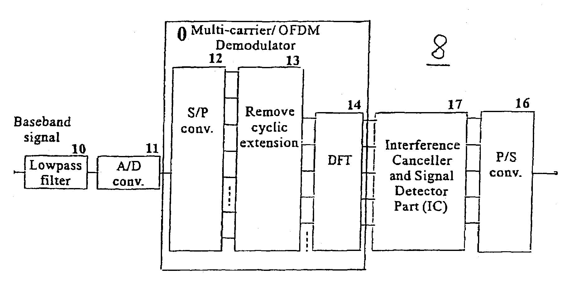
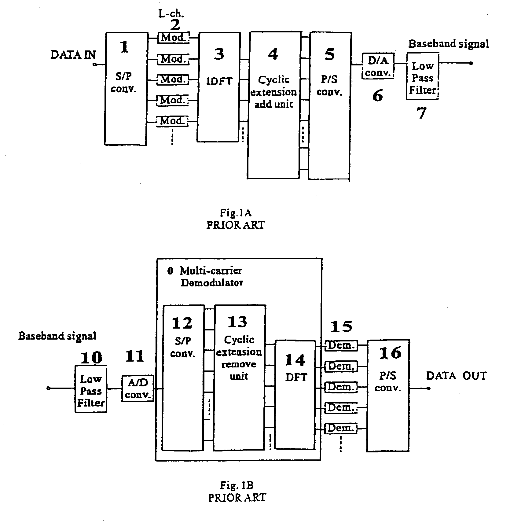
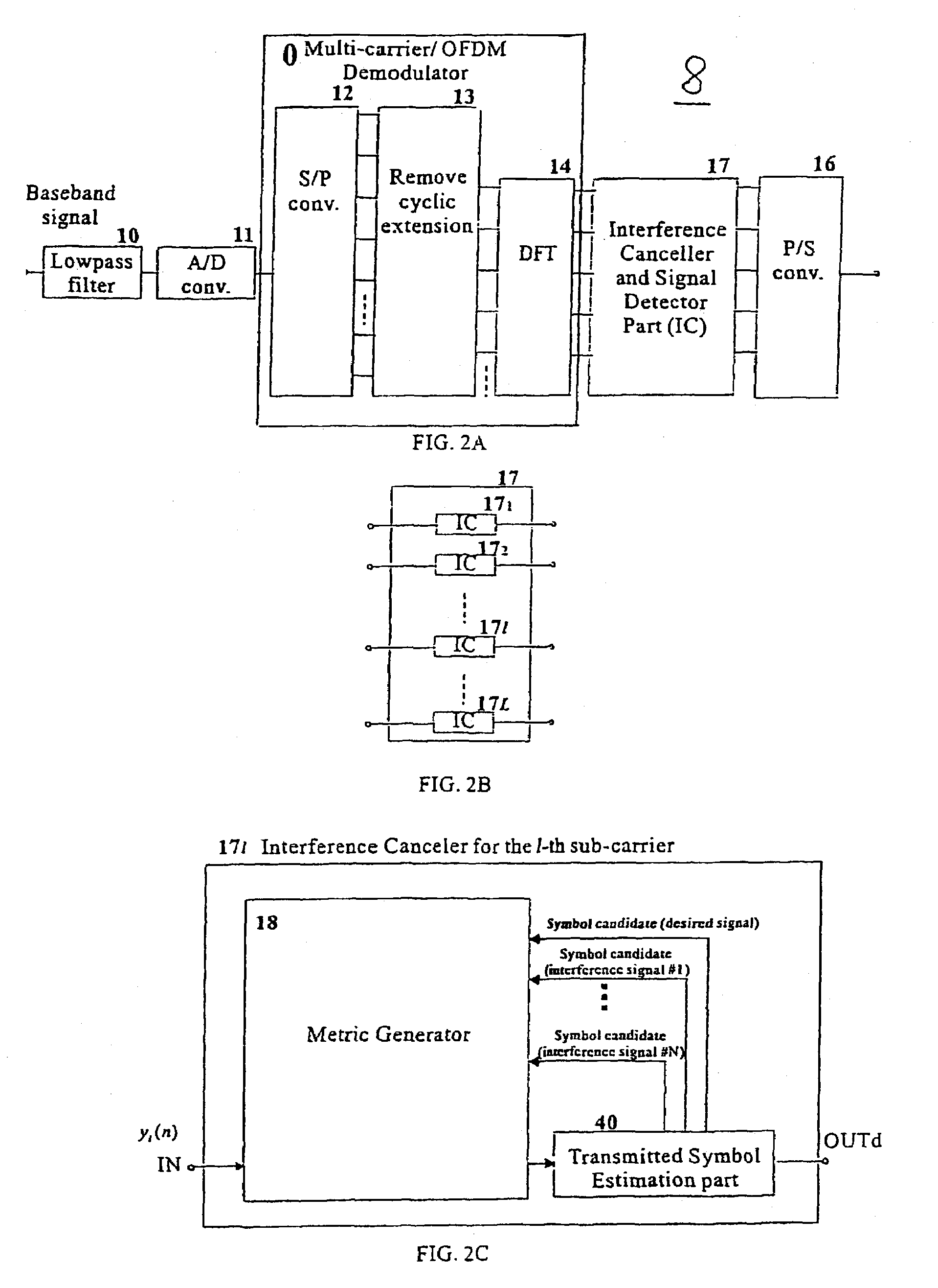
[0055]A digital signal transmission multi-carrier scheme, such as an orthogonal frequency division multiplexing scheme, called OFDM scheme, reduces the effects of inter-symbol or inter-block interference by making the block period much larger than the delay spread of the radio channel. Even when the delay spread becomes relatively large compared with the length of the OFDM block period, the use of a cyclic prefix preserves the orthogonality of the each sub-carrier channels and eliminates inter-symbol interference (ISI) or inter-block interference (IBI) between consecutive OFDM symbols. Thus, it is a great advantage for high bit rate digital signal transmissions to employ an OFDM scheme. In case of a conventional single carrier per channel (SCPC) transmission system, when the channel impulse response extends over many symbols, the number of states to be defined in a maximum likelihood sequence estimator becomes large. The number of states increases exponentially as the excess delay n...
PUM
 Abstract
Description
Claims
Application Information