Multi-arm gimbal system

Active Publication Date: 2012-03-01
BROWN GARRETT W
View PDF27 Cites 30 Cited by
  • Summary
  • Abstract
  • Description
  • Claims
  • Application Information

AI Technical Summary

Benefits of technology

[0007]The invention provides a gimbal support apparatus to support tools or other payloads for use during performance of tasks using those payloads. The payload can be selectively biased to achieve an optimum position fo

Problems solved by technology

The resulting stresses, particularly from overhead usages, or near-full extension of the arm, are a common cause of work-related shoulder and forearm injuries.
This can be a challenge because the center-of-gravity of a given tool is often located within a non-cylindrical section of the tool body, which may inhibit the installation of a gimbal bearing assembl

Method used


Image

  • Multi-arm gimbal system
  • Multi-arm gimbal system
  • Multi-arm gimbal system

Examples


Embodiment Construction

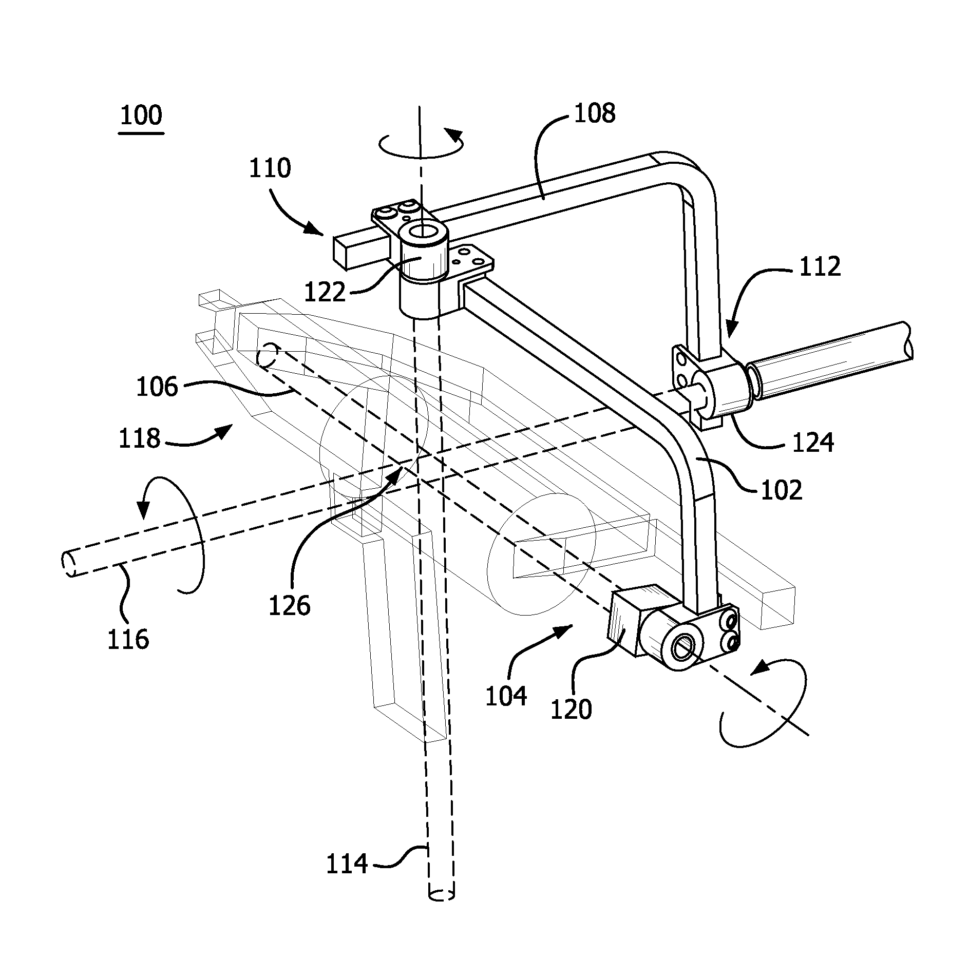
[0025]Embodiments of the invention include a gimbal support apparatus that is adjustable to selectively bias the resting position of a supported payload. The payload may be for example, a tool, workpiece, diagnostic equipment, or other object that can be supported by the apparatus.

[0026]Selective biasing can be accomplished by adjusting the point at which virtual axes of rotation of the gimbal intersect, such as at the center of gravity of the payload, or removed from the center of gravity to provide a tilted resting position. Or, if desired, the virtual axes can be adjusted so they do not all intersect at a common point. “Virtual axis” is used to describe the infinite length imaginary axis which is an extension of a bearing or other axis of rotation.

[0027]The gimbal system can provide a connection between a payload and a support arm, such as a zeroG® equipoising arm, to provide further degrees of freedom and maneuverability. In a illustrative embodiment of the invention, the gimbal...


PUM

PropertyMeasurementUnit
Lengthaaaaaaaaaa
Radiusaaaaaaaaaa
Radiusaaaaaaaaaa

Abstract

The invention provides a gimbal support apparatus to support tools or other payloads for use during performance of tasks using those payloads. The payload can be selectively biased to achieve an optimum position for performance of the task. The gimbal support apparatus comprises rotationally connected gimbal arms that can be adjusted with respect to one another and to an equipoising support arm to attain the selected payload bias.

Description

[0001]This application claims priority to U.S. Provisional Patent Application No. 61 / 377,312, filed Aug. 26, 2010.BACKGROUND OF THE INVENTION[0002]In many industrial, business and medical environments, workers are required to repetitively lift, position and orient tools and objects of significant weight, and deploy them anywhere within the reach of their arms, from low to overhead to extending out in front. The resulting stresses, particularly from overhead usages, or near-full extension of the arm, are a common cause of work-related shoulder and forearm injuries.[0003]Ergonomic equipment supports are known in the art, including ‘tool balancers’ that suspend tools on wires from retractable reels, and articulated support arms that work in conjunction with two or three-axis gimbal attachments to provide angular freedom between the arm and the supported equipment. These support systems typically require the tool to be supported at its center of gravity. This can be a challenge because ...

Claims


Application Information

Patent Timeline
IPC IPC(8): F16M11/02B23P11/00
CPCF16M11/10Y10T29/49826F16M2200/041F16M11/2071
Inventor BLACK, MICAHSACKSTEDER, ANTHONY D.
Owner BROWN GARRETT W
Why Eureka
Try Eureka