Subsurface Irrigation Mat

Active Publication Date: 2013-03-28
HUNTER INDUSTRIES
View PDF4 Cites 31 Cited by
  • Summary
  • Abstract
  • Description
  • Claims
  • Application Information

AI Technical Summary

Benefits of technology

[0007]In accordance with the present invention an improved subsurface irrigation mat includes at least one perforated tube, a web made of a first capillary textile, and a casing made of a second capillary textile. The casing surrounds substantially an entire circumference of the perforated tube along at least a portion of a length of the tube. The casing is not formed as a pocket by laminating a portion of the second capillary textile with the first capillary textile as in a prior design. At least one attachment secures the casing to the web s

Problems solved by technology

If these contoured areas are watered with sprinklers, a substantial amount of water can run-off the contoured areas or spray onto undesired areas such as walkways.
In some areas, the ambient temperature is so high that a substantial amount of water applied via sprinklers to turf and other landscaping is lost d

Method used


Image

  • Subsurface Irrigation Mat
  • Subsurface Irrigation Mat
  • Subsurface Irrigation Mat

Examples


Embodiment Construction

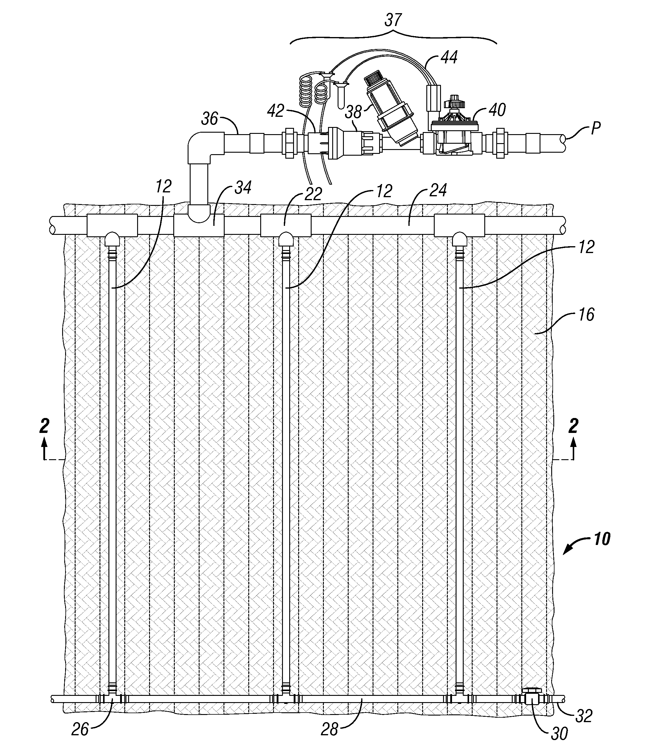
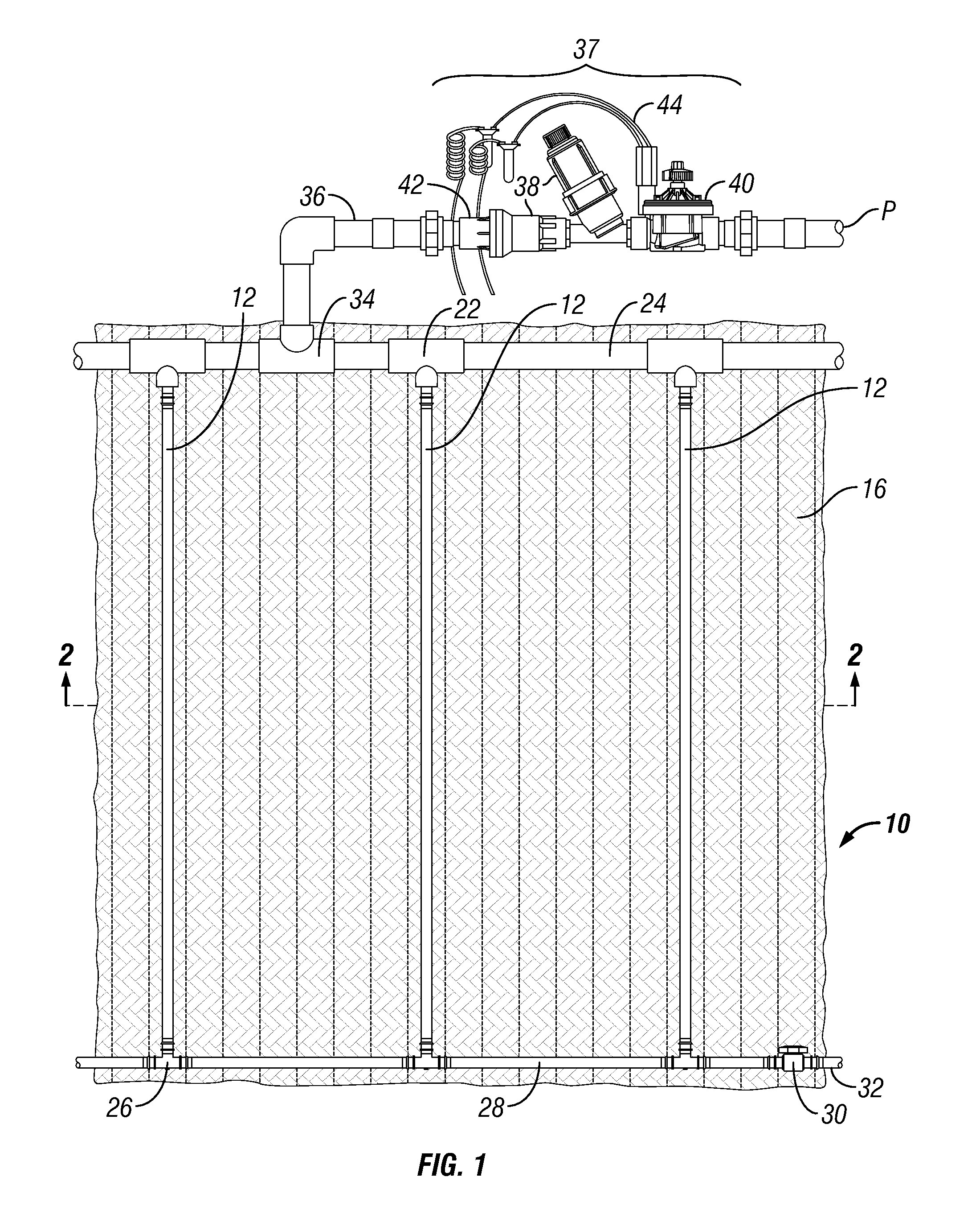
[0015]Referring to FIG. 1, in accordance with an embodiment of the present invention an improved subsurface irrigation mat 10 includes a plurality of perforated tubes in the form of drip lines 12 that extend in parallel, spaced apart fashion. The drip lines 12 contain emitters that regulate and limit the flow of water through associated holes in the tubes. By way of example, the drip lines 12 may be located at equally spaced intervals, such as thirty centimeters to sixty centimeters (approximately one to two feet) apart. Each drip line 12 is surrounded substantially along its entire length by a generally cylindrical jacket or casing 14 (FIGS. 2 and 4) made of a first capillary textile preferably in the form of non-woven polymer fleece material. The fleece casings 14 are in turn secured via adhesive 15 (FIG. 4) to the top of a continuous mat or web 16 (FIGS. 1 and 4) made of a second capillary textile, also preferably a non-woven polymer fleece material. The adhesive 15 functions as ...


PUM


Abstract

A subsurface irrigation mat includes at least one perforated tube, a web made of a first capillary textile, and a casing made of a second capillary textile. The casing surrounds substantially an entire circumference of the perforated tube along at least a portion of a length of the tube. At least one attachment secures the casing to the web so that the casing extends across the web. Water leaving through the holes in the perforated tube can saturate the casing, seep into the web from the casing, and then be carried across the web by capillary action. The result is a substantially uniform discharge of water from the web into a root zone of plants growing in a layer of a growing medium located above the web.

Description

CROSS-REFERENCE TO RELATED APPLICATIONS[0001]This application is a continuation-in-part of U.S. patent application Ser. No. 13 / 597,211, filed Aug. 28, 2012, by Thomas Roes and Todd Polderman entitled“Irrigation Mat.” Priority based on the filing date of the aforementioned pending U.S. Ser. No. 13 / 597,211 patent application is hereby claimed, the entire disclosure of which is hereby incorporated by reference. This application also claims priority based on the filing dates of three German Patent Applications: No. DE 10 2011 114 238.3 filed 26 Sep. 2011; No. DE 10 2011 083 742.6 filed 29 Sep. 2011; and No. DE 10 2011 084 468.6 filed 13 Oct. 2011.FIELD OF THE INVENTION[0002]The present invention relates to devices for irrigating turf and other landscaping.BACKGROUND OF THE INVENTION[0003]Most residential, commercial, golf and athletic field irrigation sites are watered with sprinklers which distribute the water above the ground. The sprinklers are typically coupled to solenoid actuated ...

Claims


Application Information

Patent Timeline
IPC IPC(8): A01G25/06
CPCA01G25/06
Inventor ROESS, THOMAS H.POLDERMAN, TODD D.PORTER, LA MONTE D.
Owner HUNTER INDUSTRIES
Why Eureka
Try Eureka