Take-up winding facility

A spinning and equipment technology, applied in the field of spinning and winding equipment, can solve the problems of complicated spinning and winding equipment, and achieve the effects of lowering the device height, ensuring silk quality, and improving workability

Active Publication Date: 2010-06-16
TMT MACHINERY INC
View PDF2 Cites 6 Cited by
  • Summary
  • Abstract
  • Description
  • Claims
  • Application Information

AI Technical Summary

Problems solved by technology

However, since it is necessary to additionally set a feed roller for drawing the sliver spun from the spinning machine between the spinning machine and the feeding roller arranged directly in front of the winder, there is a dense winding of the feeding roller. Near the machine, spinning and winding equipment becomes complicated

Method used


Image

  • Take-up winding facility
  • Take-up winding facility
  • Take-up winding facility

Examples


Embodiment Construction

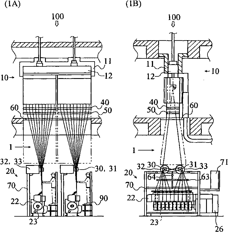
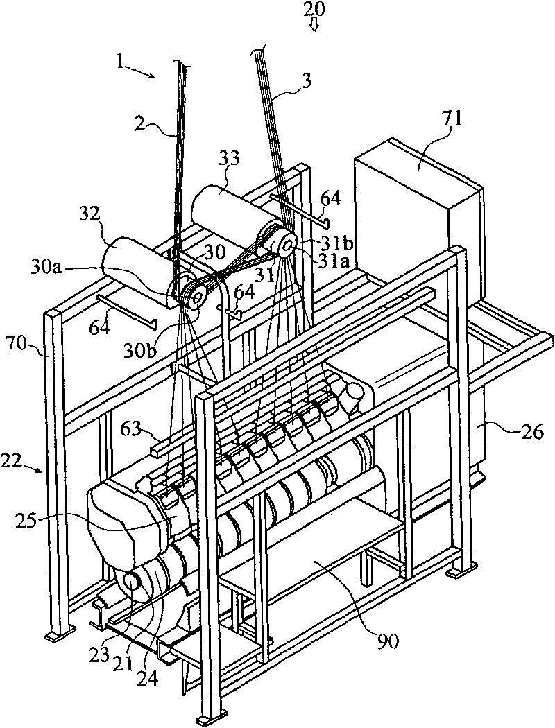
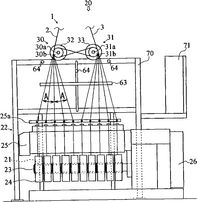
[0064] Next, a spinning winding facility 100 according to a first embodiment of the present invention will be described with reference to the drawings. figure 1 A is a front view of the spinning winding device 100 according to the first embodiment of the present invention, figure 1 B is a side view of the spinning winding device 100 according to the first embodiment of the present invention, figure 2 is a perspective view of the spinning winding device 20, image 3 It is a side view of the spinning winding device 20 . In addition, in the following description, the acting direction of gravity is taken as the vertical direction, and the axis direction of the bobbin holder shaft 23 included in the winding machine 22 described later is taken as the front-rear direction. The side to which the device 26 is connected is referred to as the rear side, and the other side is referred to as the front side. In addition, the winding machine 22 is viewed from the front side, and the dire...


PUM


Abstract

An object of the present invention is to provide a take-up winding facility which is miniaturized by reducing take-up winding device height and which is simplified by simplifying the layout of vicinity of a take-up winding machine. The present invention provides a take-up winding facility 100 configured to feed a plurality of filament yarns spun out by a spinning machine 10, from above to below to simultaneously wind the plurality of filament yarns 1 around respective plural bobbins 21 installed on a bobbin holder shaft 23 in one take-up winding machine 22, wherein a plurality of yarn feedingrollers (yarn feeding rollers 30, 31) are arranged immediately before the take-up winding machine 22, and the plurality of filament yarns 1 spun out by the spinning machine 10 are divided into a plurality of groups (filament yarn groups 2, 3) which are then fed to the respective plural yarn feeding rollers (yarn feeding rollers 30, 31) arranged immediately before the take-up winding machine 22, and the groups of filament yarns are distributively wound around respective bobbins 21 via the plurality of yarn feeding rollers (yarn feeding rollers 30, 31).

Description

technical field [0001] The invention relates to a spinning and winding device, in which a plurality of filaments spun from a spinning machine are wound by a winding machine through a plurality of rollers. Background technique [0002] As the existing spinning and winding equipment, the following equipment is provided: one winding machine is provided with one feeding roller arranged directly in front of the winding machine, and all the spun yarns are passed through the one winding machine. The front feed roller spreads out and is wound by a plurality of bobbins mounted on one winding machine (see Patent Document 1). [0003] In the spinning and winding equipment shown in Patent Document 1, when the spreading angle of the yarn from the feeding roller directly in front to the bobbin installed on the winder (the yarn path from the feeding roller to the bobbin and the vertical direction When the angle formed by the yarn) is larger than the specified angle, the friction of the ya...

Claims


Application Information

Patent Timeline
Patent Type & Authority Applications(China)
IPC IPC(8): D01D13/02B65H54/02B65H51/005B65H51/12B65H71/00
CPCB65H54/20B65H2701/3132B65H51/12B65H54/2881B65H71/007B65H51/005
Inventor 中川理
Owner TMT MACHINERY INC
Why Eureka
Try Eureka