High-power laser multipath optical fiber sampling time waveform measuring device

A multi-channel optical fiber, sampling time technology, applied in the direction of instruments, etc., can solve the problems of inconvenient system maintenance and real-time multi-channel measurement, increase system complexity, high price, etc., to improve the power balance diagnosis ability between driver bundles and measurement costs. Reduced, easy-to-integrate effects

Active Publication Date: 2011-11-09
SHANGHAI LASER POWER EQUIP CO LTD
View PDF0 Cites 0 Cited by
  • Summary
  • Abstract
  • Description
  • Claims
  • Application Information

AI Technical Summary

Problems solved by technology

Since the measurement equipment with high time resolution, such as high-speed digital oscilloscope, is expensive, and there are many measurement points in the high-power laser device parameter diagnosis system and the distance between each measurement point is relatively long, if each measurement point corresponds to a set of measurement devices, not only the cost It is expensive and increases the complexity of the system, which is not convenient for system maintenance and real-time multi-channel measurement

Method used


Image

  • High-power laser multipath optical fiber sampling time waveform measuring device
  • High-power laser multipath optical fiber sampling time waveform measuring device
  • High-power laser multipath optical fiber sampling time waveform measuring device

Examples


Embodiment Construction

[0026] The present invention will be further described in detail below in conjunction with the embodiments and the accompanying drawings.

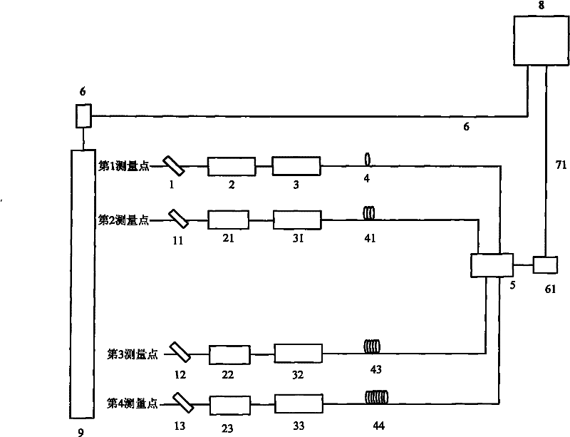
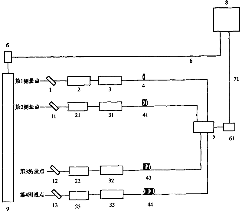
[0027] see first figure 1 , figure 1 It is a schematic diagram of the optical path structure of the embodiment of the high-power laser multi-channel optical fiber sampling time waveform measuring device of the present invention. As can be seen from the figure, the composition of the high-power laser multi-channel optical fiber sampling time waveform measuring device of the present invention includes:

[0028] High-speed digital oscilloscope 8 and high-power laser 9 to be tested;

[0029] The first input terminal of the high-speed digital oscilloscope 8 is connected by the first photodetector 6 through the first cable 7 to form an external trigger circuit:;

[0030] Multiple sampling optical paths are set at multiple points to be measured of the high-power laser 9 to be measured: each sampling optical path is connected in sequence with s...


PUM


Abstract

The invention relates to a high-power laser multipath optical fiber sampling time waveform measuring device which is characterized by comprising a high-speed digital oscilloscope and a high-power laser to be measured; a first photoelectric detector is connected with the first input end of the high-speed digital oscilloscope through a first cable to form an external trigger circuit; multiple pathsof sampling optical paths are arranged at plurality of points to be measured of the high-power laser to be measured; each path of sampling optical path comprises a sampling mirror, an optical attenuator, a coupling device and a sampling optical fiber which are sequentially connected; and the sampling optical fibers of the multiple paths of sampling optical paths are connected with the input end of an optical fiber combiner, the output end of the optical fiber combiner is connected with a second photoelectric detector, and the output end of the second photoelectric detector is connected with the second input end of the high-speed digital oscilloscope through a second cable. The invention has the advantages of small volume, strong anti-interference capability, adjustable length, flexible light beam guidance, convenient integrated control and the like.

Description

technical field [0001] The invention relates to high-power laser time waveform measurement, in particular to a high-power laser multi-channel optical fiber sampling time waveform measurement device. Background technique [0002] The research and development of inertial confinement fusion (ICF) put forward very strict requirements on the driving laser and its diagnostic system. The uniformity of the temperature of the target sphere in the black cavity target and the generation of epithermal electrons are closely related to the macroscopic parameters (energy, number of beams, arrangement) and detailed parameters of the driving laser. One of the most important indicators in the detailed parameters is the power balance of each laser. The content of power balance includes the energy balance and waveform consistency of each beam pulse. At present, for the driving laser whose pulse width is on the order of nanoseconds, the measurement of its time characteristics is limited to the...

Claims


Application Information

Patent Timeline
Patent Type & Authority Patents(China)
IPC IPC(8): G01J11/00
Inventor 曹婧朱宝强杨琳唐顺兴张春香高妍琦
Owner SHANGHAI LASER POWER EQUIP CO LTD
Why Eureka
Try Eureka