Double-blade boring cutter head without radial motion for cutter bar

A technology of radial movement and boring tool, applied in the direction of tool holder, etc., to achieve the effect of high efficiency, enhanced stability and good quality

Active Publication Date: 2012-05-02
CHENGDU AIRCRAFT INDUSTRY GROUP +1
View PDF0 Cites 0 Cited by
  • Summary
  • Abstract
  • Description
  • Claims
  • Application Information

AI Technical Summary

Problems solved by technology

[0003] In order to solve the radial feed during the cutting process of the telescopic double-edged deep hole boring tool system

Method used


Image

  • Double-blade boring cutter head without radial motion for cutter bar
  • Double-blade boring cutter head without radial motion for cutter bar
  • Double-blade boring cutter head without radial motion for cutter bar

Examples


Embodiment Construction

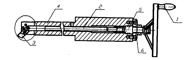
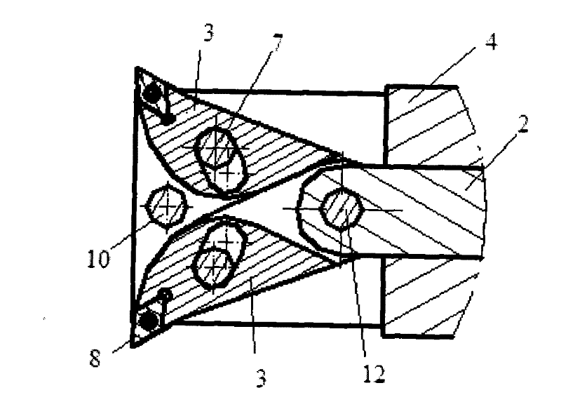
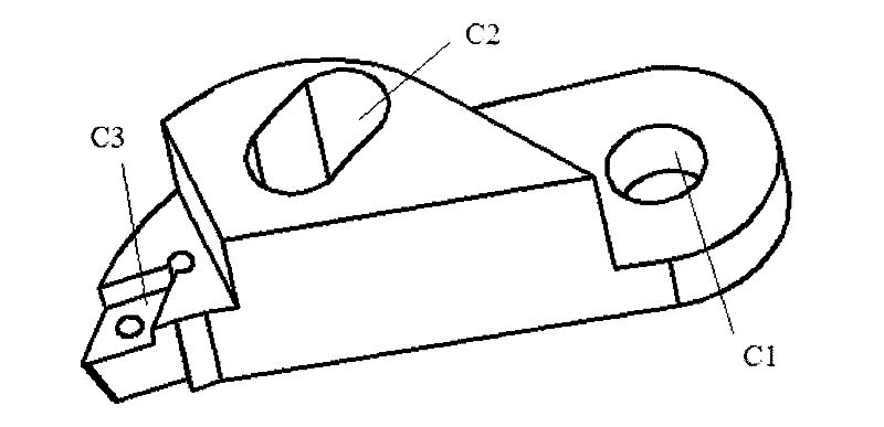
[0014] exist figure 1 In the embodiment of the telescopic double-edged deep hole boring tool described, the central axis of the boring bar (4) is formed with a through hole passing through the axis, and a pusher for connecting the radial feed mechanism of the bar head of the boring bar (4) is installed in the through hole. The rod (2) is provided with a rotary handle (1) at its rear end. The rotary handle (1) rotates the screw rod (5) to push the push rod (2) to perform axial telescopic movement in the through hole of the boring bar. The push rod (2) drives the tool holder (3) connected thereon with the movement mode of pulling or pushing, and the cutter holder (3) is connected with the push rod (2) by a rotating pin (12) rotating pair. The guide chute (C2) on the tool seat (3) is linked with the fixing screw (7) to move the pair. When the push rod (2) is pulled or pushed, the tool seat (3) moves along the direction along its guide chute (C2) chute under the action of a rota...


PUM


Abstract

The invention provides a double-blade boring cutter head without radial motion for a cutter bar, aiming to provide a stable and reliable boring cutter head capable of reducing the self-excited vibration of a boring bar. The double-blade boring cutter head comprises a cutter base which is fixedly connected to the end head of a boring bar (4) and can be used for replacing a blade; and the cutter base comprises two symmetrical crescent base bodies in a shear fork shape, wherein end part same-hole shafts of the two symmetrical crescent base bodies can be rotatably connected to a sunken platform of a push rod (2) and the boring bar (4). Since the two symmetrical crescent base bodies in a shear fork shape are used, the cutter bar does not do radial motion but can realize self-radial feeding in the boring and cutting process. By the invention, radial cutting forces of two blades on the boring cutter head can be mutually offset, so that asymmetrical unidirectional forced condition of the cutter bar can be changed; and the boring bar is not a cantilever beam single side of which is forced any longer and cannot generate the phenomena of deviation of blade center, cutter relieving or cutter scraping like a single-blade boring cutter.

Description

technical field [0001] The invention relates to a cutter head for a telescopic double-edged boring bar. Background technique [0002] In the prior art, during the boring process, the cutter head fixedly connected to the boring bar, under the action of continuous cutting force, the boring bar produces self-excited vibration, which often leads to a reduction in the precision and surface quality of the processed workpiece. The tool used is a one-way insert fixed radially on the boring bar, and is generally a non-adjustable fixed device during machining. The radial feed of the cutter is accomplished by the radial movement of the cutter rod. Under the action of cutting force, the tool bears a large shear stress, which causes the blade to generate vibration amplitude, resulting in unstable and reduced processing quality. Due to the cantilever beam structure of the single-edged boring bar, the tangential cutting force causes the center of the cutting edge to deviate during proces...

Claims


Application Information

Patent Timeline
Patent Type & Authority Patents(China)
IPC IPC(8): B23B29/04
Inventor 张文光赵苏军张林丁国富谢斌斌马术文张静海
Owner CHENGDU AIRCRAFT INDUSTRY GROUP
Why Eureka
Try Eureka