

Magnetic brake controller
A technology for braking electromagnets and controllers, which is applied to electromagnets with armatures, electromagnets, electrical components, etc., can solve the problems of high power consumption, heavy weight, and many circuit components.
- Summary
- Abstract
- Description
- Claims
- Application Information
AI Technical Summary
Problems solved by technology
Method used
Image

Examples
Embodiment Construction
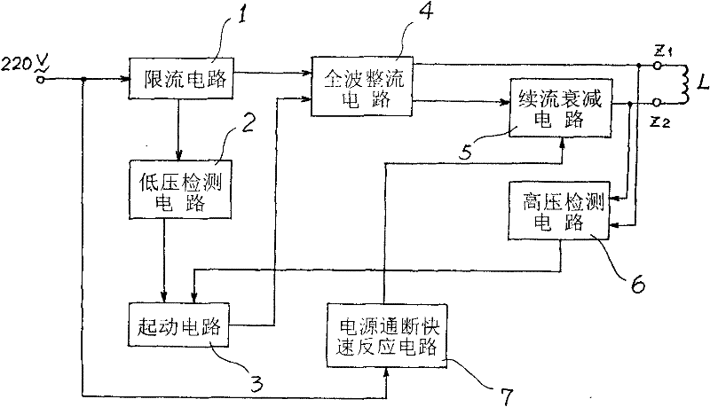
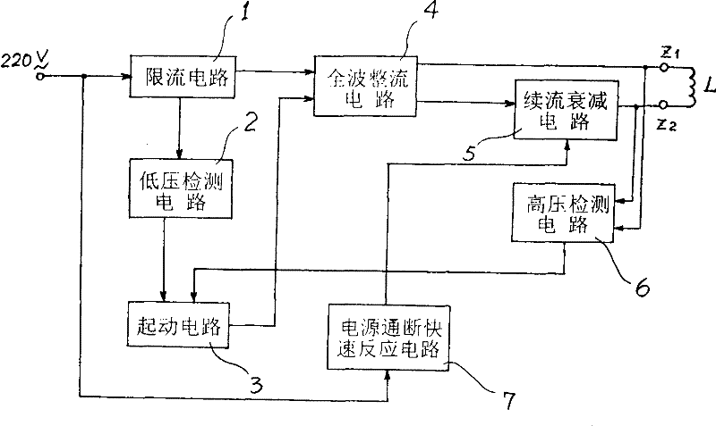
[0017] Such as figure 1 As shown, the electromagnet controller of the present invention includes a limited current circuit 1, a low-voltage detection circuit 2, a starting circuit 3, a full-wave rectification circuit 4, a freewheeling attenuation circuit 5, a high-voltage detection circuit 6, and a power supply on-off quick response circuit 7. part. Among them, the input end of the current limiting circuit 1 is used to connect to the AC power supply, the current limiting circuit 1 has two outputs, the first output is connected to the input end of the low voltage detection circuit 2, and the second output is connected to the full wave rectification circuit 4 Input terminal; the output terminal of the low-voltage detection circuit 2 is connected to the input terminal of the starting circuit 3, the output terminal of the starting circuit 3 is connected to the input terminal of the full-wave rectification circuit 4, and the output terminal of the full-wave rectification circuit 4 ...
PUM
 Abstract
Description
Claims
Application Information