Magnetic Reactor

A magnetron reactor, reactor technology, applied in the direction of electrical components, transformer/inductor coil/winding/connection, electrical component structure association, etc., can solve the problems of increasing equipment cost and manufacturing complexity, etc.

Inactive Publication Date: 2016-09-14
北京三得普华科技有限责任公司 +1
View PDF5 Cites 0 Cited by
  • Summary
  • Abstract
  • Description
  • Claims
  • Application Information

AI Technical Summary

Problems solved by technology

Another way is to increase the response speed by adding an additional set of windings. However, this method increases the cost and manufacturing complexity of the equipment, and is not an ideal choice.

Method used


Image

  • Magnetic Reactor
  • Magnetic Reactor
  • Magnetic Reactor

Examples


Embodiment 1

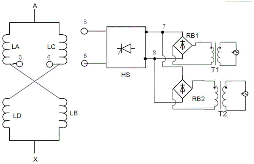
[0021] figure 1 is the circuit schematic diagram of the magnetron reactor provided in this embodiment, as figure 1 As shown, the magnetic control reactor of the present invention includes: a reactor winding, a power circuit and a demagnetization circuit HS, and the demagnetization circuit HS is connected between the output end of the power circuit and the coil of the reactor winding.

[0022] The reactor winding includes two iron cores, each of which is wound with two sets of coils, one iron core has a coil LA and a coil LD, and the other iron core has a coil LB and a coil LC. The outlet end of the coil LA is connected to the inlet end of the coil LB, the outlet end of the coil LC is connected to the inlet end of the coil LD, and the four groups of coils are in a cross-parallel structure. A group of coils on each of the iron cores is provided with a first tap, the first tap 5 is drawn from the outlet end of the coil LA, the first tap 6 is drawn from the outlet end of the coil...

Embodiment 2

[0044] Figure 5 is the circuit schematic diagram of the magnetron reactor provided in this embodiment, as Figure 5 As shown, the magnetic control reactor of the present invention includes: a reactor winding, a demagnetization circuit HS and a power supply circuit. The only difference from Embodiment 1 is that the reactor winding used in this embodiment is a non-fast common reactor winding body, and the present invention does not limit the specific form of the reactor winding.

[0045] Compared with Embodiment 1, the reactor winding of this embodiment also leads to the second tap 1 in the middle of the coil LA, and the second tap 3 is drawn in the middle of the coil LD, and a controllable tap is connected between the second tap 1 and the second tap 3 Device MS1, the second tap 2 is drawn in the middle of the coil LC, the second tap 4 is drawn in the middle of the coil LB, the controllable device MS2 is connected between the second tap 2 and the second tap 4, and the controll...

Embodiment 3

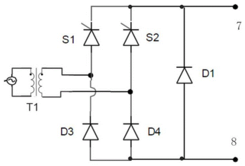
[0049] Image 6 is the circuit schematic diagram of the magnetron reactor provided in this embodiment, as Image 6 As shown, the magnetic control reactor of the present invention includes: a reactor winding, a demagnetization circuit HS and a power supply circuit. Compared with Embodiment 1, the power supply circuit adopted in this embodiment only includes the first rectifier bridge RB1.

[0050] At this time, the first rectifier bridge RB1, as a controllable rectifier bridge, can control the output voltage by changing the conduction angle of the controllable device according to the instruction of the control system. When the isolation transformer T1 provides a higher power supply voltage to the first rectifier bridge RB1, due to the difference in conduction angle, the first rectifier bridge RB1 can output a lower voltage, thereby maintaining a lower output current and making the reactor work in normal regulation. When fast excitation is required, changing the conduction an...


PUM


Abstract

The invention relates to a magnetically-controlled reactor. The magnetically-controlled reactor comprises the following components of: a reactor winding which includes iron cores and coils of which the current magnitude is utilized to change the magnetic flux of the iron cores, wherein the coils are wound around the iron cores; a power supply circuit which is used for generating work current and outputting the current to the coils; a demagnetization circuit which is connected between the output end of the power supply circuit and the coils of the reactor winding and is used for disconnecting the current that is outputted to the coils by the power supply circuit so as to fast decrease the current of the coils and accelerate the demagnetization of the iron cores. With the magnetically-controlled reactor adopted, fast demagnetization can be realized, and tap voltage and an additional excitation winding are not needed to be increased.

Description

technical field [0001] The invention relates to a reactor device for reactive power compensation, in particular to a magnetron reactor. Background technique [0002] Magnetically Controlled Reactor (MCR), as a type of static var compensation device, originated from magnetic amplifiers and saturable reactors, but is fundamentally different from saturable reactors in terms of structure and performance. The technology of magnetron reactor was made a breakthrough in the former Soviet Union and was introduced into China at the end of the last century. It has the advantages of high reliability, low loss, less land occupation, less harmonic pollution, and easy control. It is widely used in mines, In industries such as metallurgy and electric power, it has become the main choice to replace thyristor-controlled reactors. [0003] The basic working principle of the magnetic control reactor is that the magnetic flux on the iron core can be changed by controlling the DC current in the ...

Claims


Application Information

Patent Timeline
Patent Type & Authority Patents(China)
IPC IPC(8): H02P13/00H02J3/18H01F27/30H01F27/40
CPCY02E40/30
Inventor 王志泳
Owner 北京三得普华科技有限责任公司
Why Eureka
Try Eureka