Pump rotor for a canned motor pump

A technology of shielding pumps and rotors, which is applied to the components, pumps, and pump devices of pumping devices for elastic fluids, can solve problems such as being difficult to minimize, and achieve the effects of minimizing unbalance, reducing unbalance, and reliable sealing.

Inactive Publication Date: 2010-08-11
ROBERT BOSCH GMBH
View PDF2 Cites 12 Cited by
  • Summary
  • Abstract
  • Description
  • Claims
  • Application Information

AI Technical Summary

Problems solved by technology

[0004] It is thus difficult to minimize the unbalance of the pump rotor of such conventional canned pumps, since the impeller and rotor unit can only be positioned on the shaft with limited precision due to manufacturing and assembly tolerances

Method used


Image

  • Pump rotor for a canned motor pump
  • Pump rotor for a canned motor pump
  • Pump rotor for a canned motor pump

Examples


Embodiment Construction

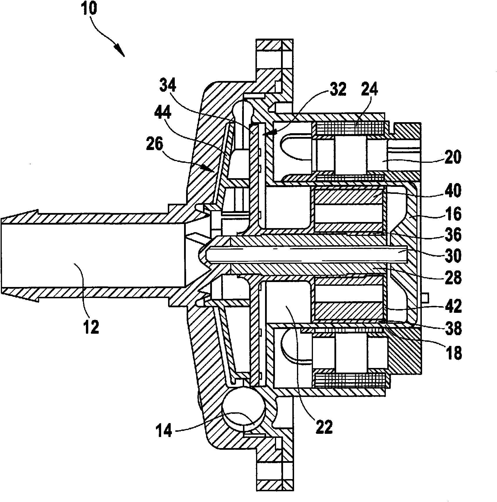
[0025] exist Figures 1 to 3b A first embodiment of the invention is shown in . Depend on figure 1 It can be seen that the canned pump 10 comprises inflow and outflow channels 12 , 14 for the liquid to be pumped, for example the coolant in the cooling circuit of the internal combustion engine, and that the engine housing 16 is designed in such a way that it is divided into stems by slots 18 . Chamber 20 and wet chamber 22, which are respectively sealed relative to each other.

[0026] Within the dry chamber 20 are located a stator 24 and control electronics for driving the pump's electric motor. In the wet chamber 22 , the pump rotor 26 is rotatably supported by means of a bearing bush 28 on a shaft 30 which is fixedly mounted in the motor housing 16 .

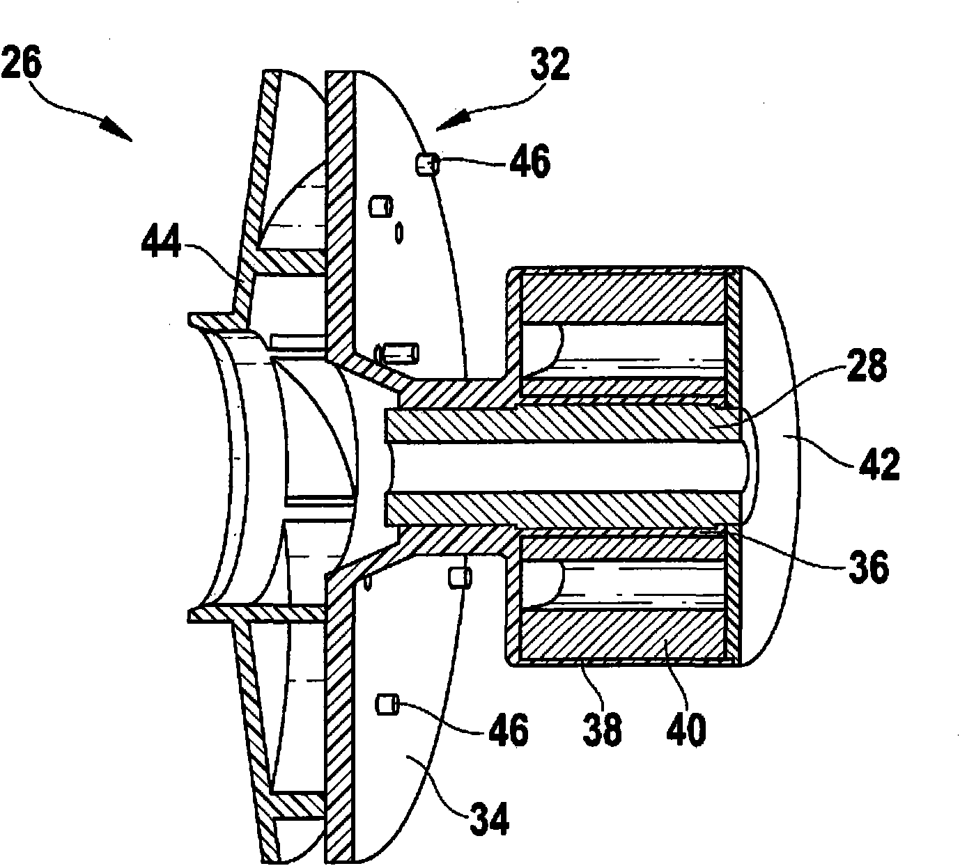
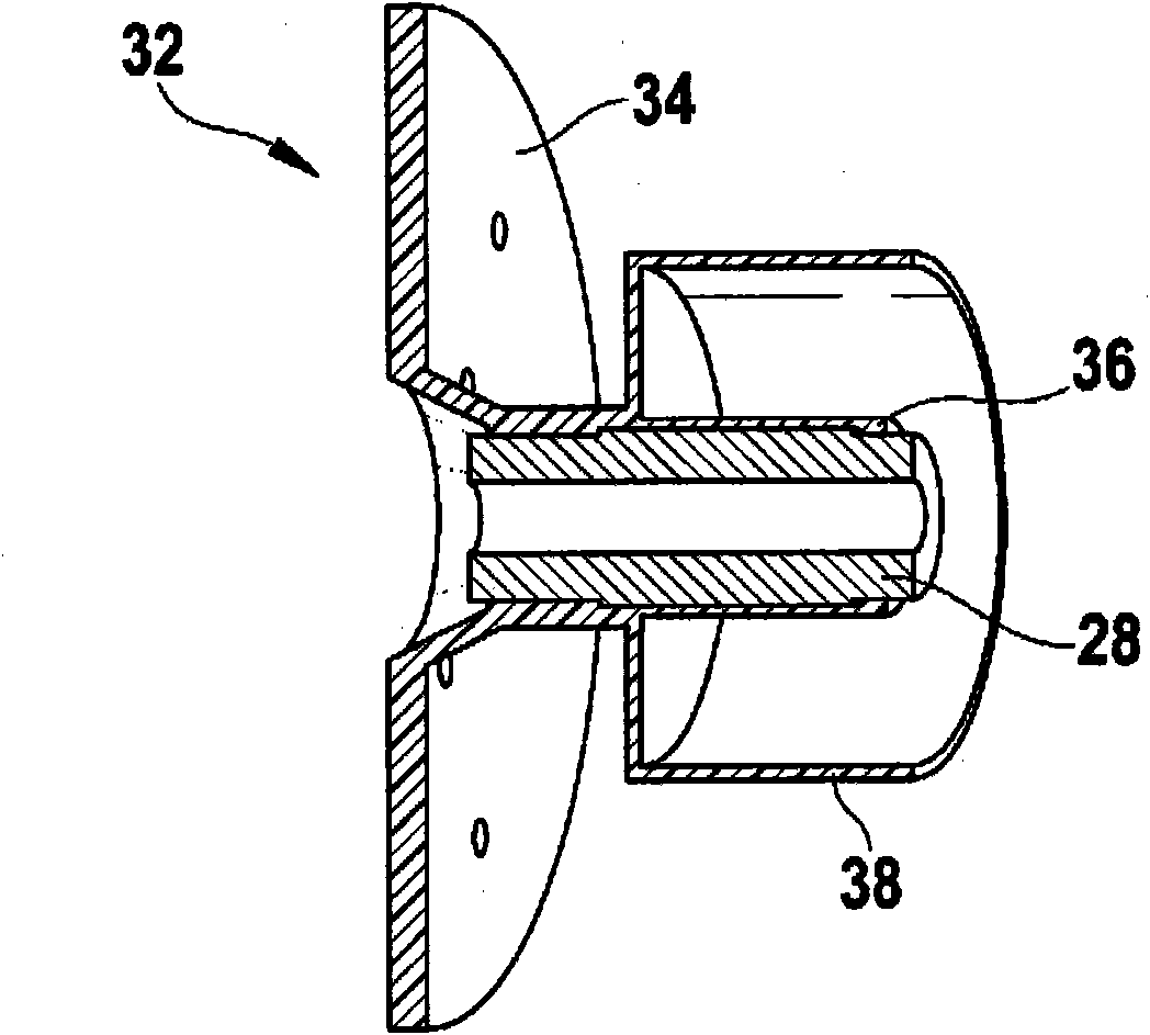
[0027] The pump rotor 26 includes a one-piece base body 32 having an impeller base plate 34 , a rotor receiving bushing 36 and a receiving sleeve 38 for receiving the rotor unit 40 . The open side of the receiving sleeve 3...


PUM


Abstract

The invention relates to a pump rotor (26) for a canned motor pump. The pump rotor (26) comprises a base body (32) designed in one piece, with an impeller base disk (34) and a rotor holder bushing (36) and a rotor unit (40) with rotor magnets that are arranged on the rotor holder bushing (36).

Description

technical field [0001] The invention relates to a pump rotor, in particular for canned pumps in which slotted tubes are used. Background technique [0002] Conventional canned pumps for pumping liquids, such as those used in cooling systems of motor vehicles, have an impeller arranged on the shaft. The electric motor is used to drive the impeller, whose rotor unit is arranged on the same shaft as the impeller to avoid complex gearing and is also exposed to the liquid to be pumped. In order to protect the stator and the control electronics of the electric motor from liquids, a sealing seam on the motor housing is provided between the rotor unit and the stator. [0003] Such canned pumps are known, for example, from EP 1 281 870 A2 or US 7,704,019 B2. In these known pumps, both the impeller and the sleeve for receiving and sealing the rotor unit are each constructed as separate parts, which can each be connected to a common hollow shaft. [0004] It is therefore difficult t...

Claims


Application Information

Patent Timeline
Patent Type & Authority Applications(China)
IPC IPC(8): F04D13/06
CPCF04D29/20F04D13/0606
Inventor C·海尔C·穆谢尔克诺茨
Owner ROBERT BOSCH GMBH
Why Eureka
Try Eureka