

Discharge lamp and method for producing a discharge lamp
A technology for discharge lamps and discharge capacitors, applied in the manufacture of discharge tubes/lamps, discharge lamps, high-pressure discharge lamps, etc., can solve problems such as failure and lamp damage, and achieve the effect of reducing lamp failure
- Summary
- Abstract
- Description
- Claims
- Application Information
AI Technical Summary
Problems solved by technology
Method used
Image

Examples
Embodiment Construction
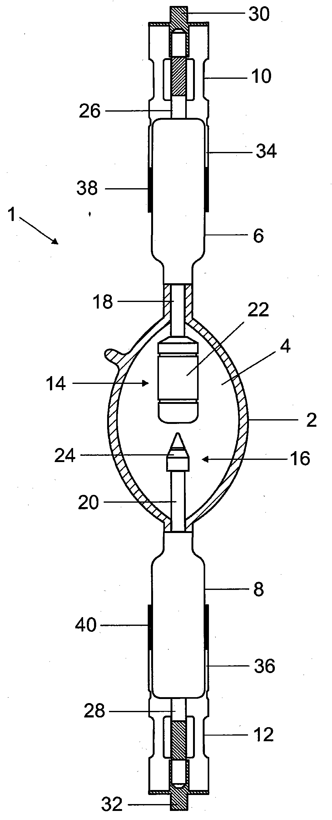
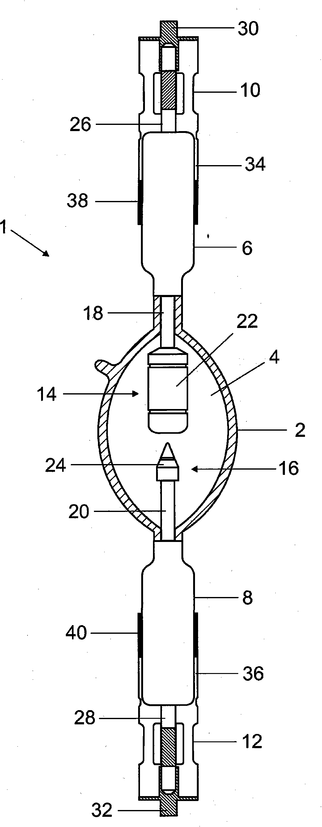
[0018] The invention is explained below on the basis of an exemplary embodiment of a xenon high-pressure discharge lamp 1 . Such lamps contain absolutely no mercury and are therefore particularly environmentally friendly. However, the invention is not limited to xenon lamps but in other lamp types, for example xenon high-pressure discharge lamps, which are suitable for use in mercury-containing lamps, have a very long operating life and produce light that is very similar to natural light. Therefore, this discharge lamp is best used in projectors, stage spotlights and aircraft headlights.
[0019] The so-called "burner" of the discharge lamp 1 has a discharge vessel 2 made of quartz glass, which has an inner cavity 4 and two radially arranged sealed bulb stems 6, 8, on which bulb stems 6, 8 is respectively provided with lamp cover 10,12. The cap sockets 10 , 12 do not have to be—as in the prior art—designed to be elastic. Two electrodes 14 , 16 formed coaxially with one anot...
PUM
 Abstract
Description
Claims
Application Information