Single-fire-wire electronic switch and control method thereof

A technology of electronic switch and control method, which is applied in the direction of energy-saving control technology, electric light source, electric lamp circuit layout, etc., can solve the problems that the single live wire electronic switch cannot solve the problem of dimming and cannot be used normally, and achieve the effect of avoiding light flickering

Inactive Publication Date: 2010-12-15
GUANGDONG TRI SUN ELECTRONICS TECH
View PDF3 Cites 8 Cited by
  • Summary
  • Abstract
  • Description
  • Claims
  • Application Information

AI Technical Summary

Problems solved by technology

[0002] In the smart home control system, the power supply mode of home appliance controllers (such as lighting controllers) requires zero and live wires. Newly renovated users can solve this problem through wiring, but for users who have already renovated, only one live wire reaches the control system. device, it will not be able to be used normally when facing this kind of user, so the single live wire switch came into being
At present, the single live wire switches on the market are limited to switch functions, but traditional users have the need for dimming in traditional AC switches, and single live wire electronic switches cannot solve the problem of dimming
At present, there is no dimmable electronic switch based on single live wire on the market

Method used


Image

  • Single-fire-wire electronic switch and control method thereof
  • Single-fire-wire electronic switch and control method thereof
  • Single-fire-wire electronic switch and control method thereof

Examples


Embodiment 1

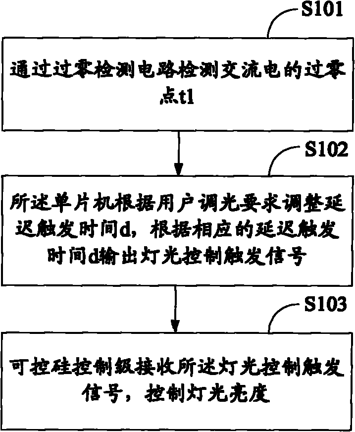
[0024] as attached figure 1 As shown: the single live wire electronic switch control process provided in the embodiment of the present invention includes:

[0025] S101: Detect the zero-crossing point t1 of the alternating current through the zero-crossing detection circuit;

[0026] S102: The single-chip microcomputer adjusts the delayed trigger time δ according to the user's dimming requirement, and outputs a light control trigger signal according to the corresponding delayed trigger time δ;

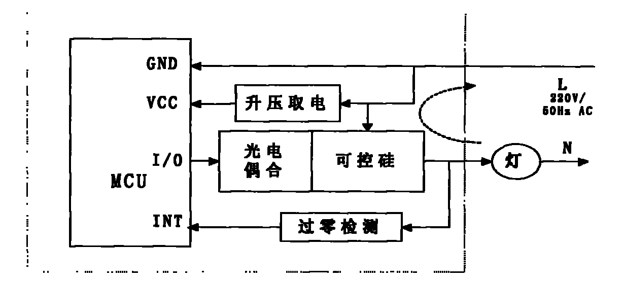
[0027] S103: The thyristor control stage receives the lighting control trigger signal, and controls the brightness of the lighting. Such as figure 2 As shown, the single live wire electronic switch includes a single chip microcomputer, a thyristor, a zero-crossing detection circuit and other single live wire switch circuits.

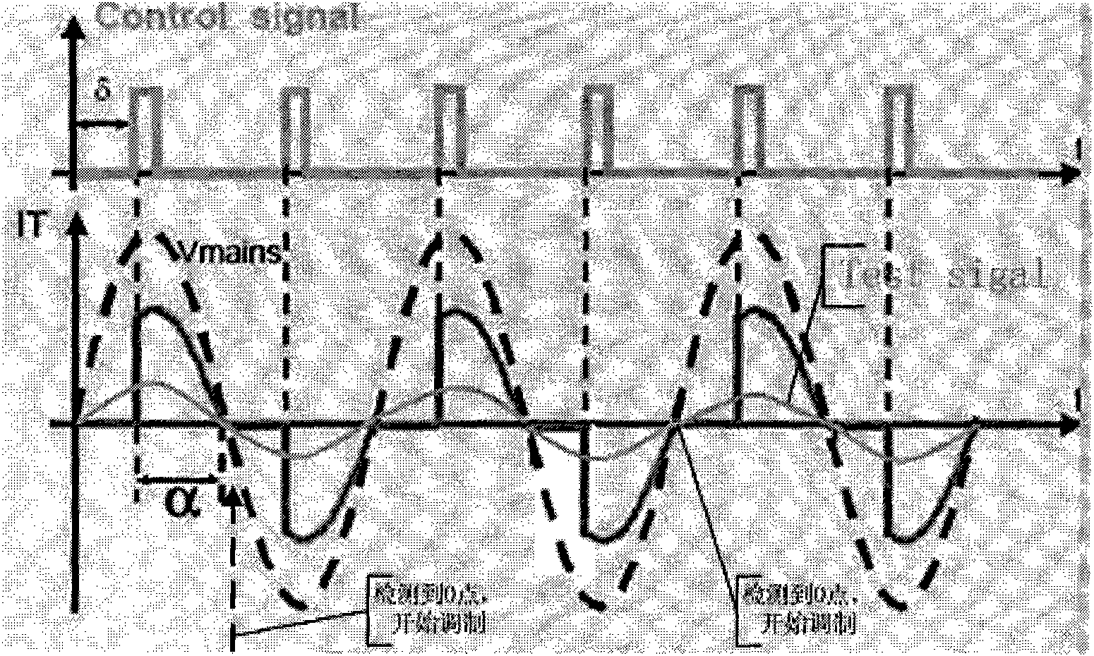
[0028] Such as image 3 As shown, the upper pulse signal is the light control trigger signal output by the microcontroller, the dotted line (Vmains) is the ...

Embodiment 2

[0032] In view of the flickering defect in the dimming process of Embodiment 1, the present invention also proposes an embodiment. Since we do not detect the starting point through hardware for the half-cycle current flowing from L to N direction, it can be seen from the above that the detected 0 point Inaccurate, we all know that the domestic mains standard is 50Hz, so we use time to determine the moment of current reversal, the MCU will generate an interrupt at a timing of 10ms, and start timing. through SCRs, such as Figure 5 shown. Similarly, if the cycle of the alternating current is T, the range of the delayed trigger time δ is 0˜T / 2.

[0033] According to the above-mentioned modulation method, use the MCU timer T0 to send out the light control trigger signal, and use the timer T1 to generate a 0-point interrupt at regular intervals. After the dimming control starts, after a 0-crossing signal is detected on the hardware (the rising edge triggers an interrupt), the tim...


PUM


Abstract

The invention relates to an electronic switch technology, in particular to a single-fire-wire electronic switch and a control method thereof. The single-fire-wire electronic switch comprises a singlechip, an SCR (Semiconductor Control Rectifier) and a zero-crossing detection circuit. The method comprises the following steps of: detecting a zero-crossing point t1 of alternate current through the zero-crossing detection circuit; adjusting a delay triggering time theta according to the dimming requirement of a user and outputting a light control triggering signal according to the corresponding delay triggering time theta by the singlechip; and receiving the light control triggering signal by the controlling stage of the SCR to control the light brightness. The invention realizes the dimming control of the single-fire-wire electronic switch.

Description

technical field [0001] The invention relates to an electronic switch, in particular to a single live wire electronic switch and a control method thereof. Background technique [0002] In the smart home control system, the power supply mode of home appliance controllers (such as lighting controllers) requires zero and live wires. Newly renovated users can solve this problem through wiring, but for users who have already renovated, only one live wire reaches the control system. Device, when facing this kind of user, it will not be able to use normally, so the single live wire switch came into being. At present, the single live wire switches on the market are limited to switching functions, but traditional users have dimming needs in traditional AC switches, and single live wire electronic switches cannot solve the problem of dimming. At present, there is no dimmable electronic switch based on a single live wire on the market. Contents of the invention [0003] In view of t...

Claims


Application Information

Patent Timeline
Patent Type & Authority Applications(China)
IPC IPC(8): H05B37/02
CPCY02B20/42Y02B20/40
Inventor 吴观明卢坚
Owner GUANGDONG TRI SUN ELECTRONICS TECH
Why Eureka
Try Eureka