Radio frequency coaxial connector

A radio frequency coaxial and connector technology, applied in the direction of connection, two-part connection device, clamping/spring connection, etc., can solve the problem of insertion loss and voltage standing wave ratio that are difficult to drop, and the cable core wire has a small elastic clamping force and is difficult to Adapt to issues such as signal attenuation to achieve the effects of reducing resource consumption, flexible holding and reliable holding, and weight reduction

Inactive Publication Date: 2011-01-26
镇江市丹徒区佳兴电子有限公司
View PDF6 Cites 6 Cited by
  • Summary
  • Abstract
  • Description
  • Claims
  • Application Information

AI Technical Summary

Problems solved by technology

In actual use, on the one hand, the signal current passing surface of such an electrical connection method is a small point, and the high-frequency signal must be seriously attenuated through such an electrical connection, and the insertion loss and voltage standing wave ratio are difficult to decrease; on the other hand , the elastic gripping force of the mating tail piece on the cable core wire is too small, which is reflected in the needle insertion hanging weight test index of only 64 grams
The existing RF coaxial connectors with such a structure are difficult to meet the increasing requirements of users for small signal attenuation and more reliable elastic holding in electrical performance connections.

Method used


Image

  • Radio frequency coaxial connector
  • Radio frequency coaxial connector
  • Radio frequency coaxial connector

Examples


Embodiment Construction

[0018] Below in conjunction with accompanying drawing the implementation details of the present invention are described as follows:

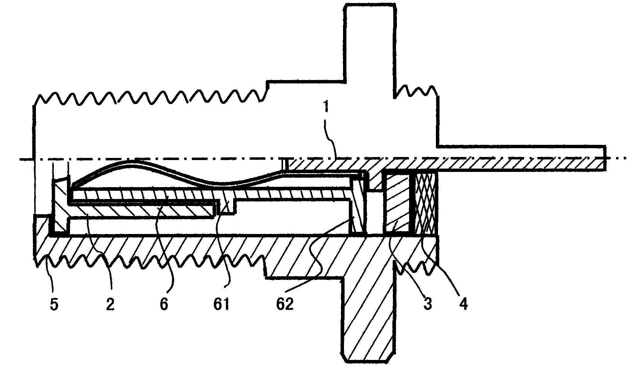
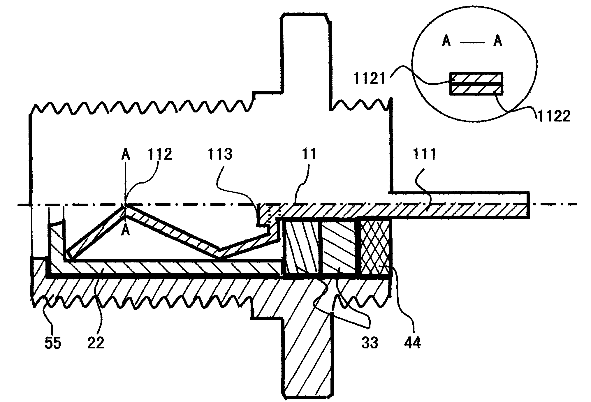
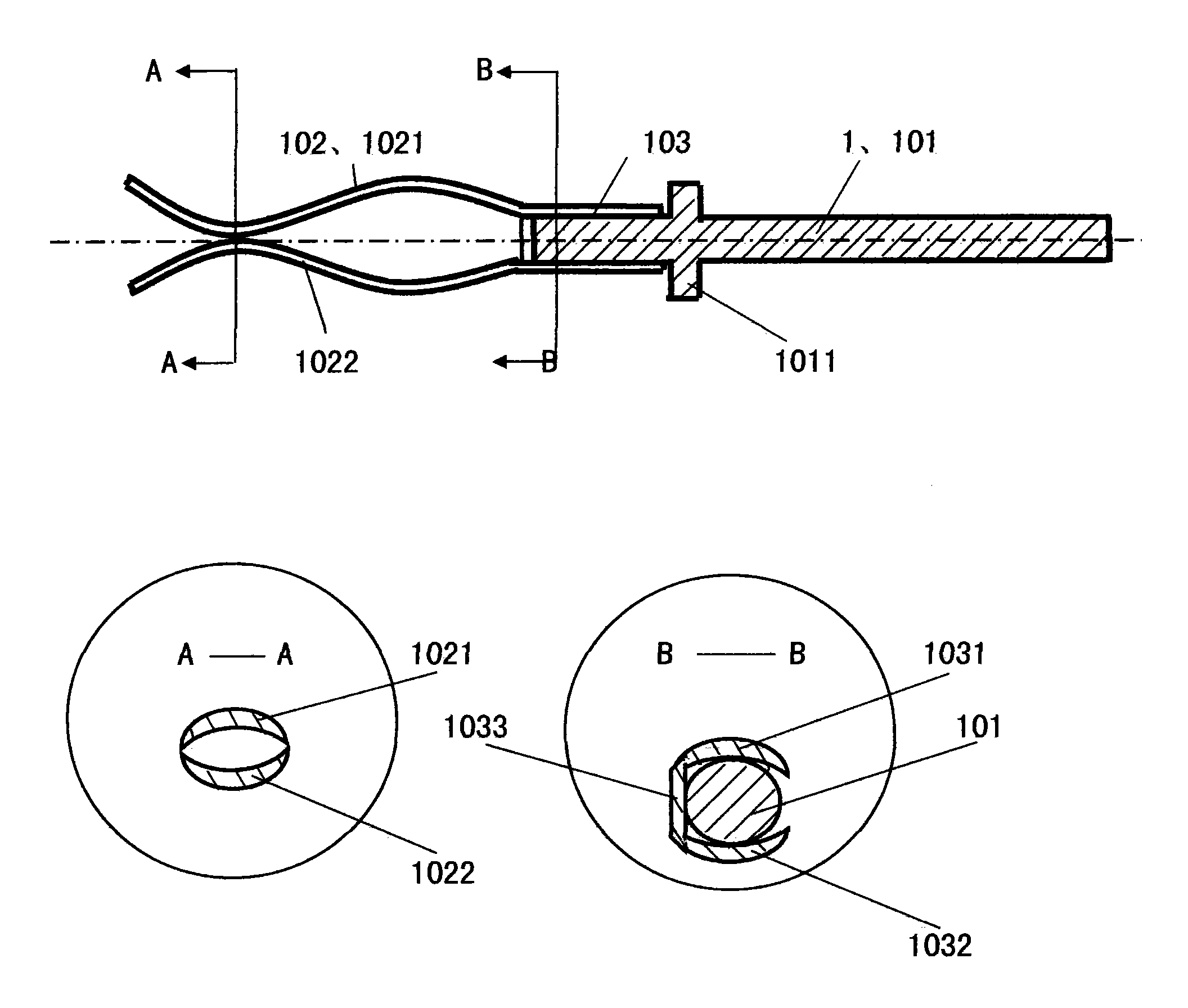
[0019] like figure 1 , 3 As shown, a radio frequency coaxial connector includes an inner conductor 1 composed of a pin head 101 and a pin tail 102, and an insulating sleeve 2 that is socketed on the outer periphery of the pin tail of the inner conductor, and is sequentially socketed on the pin head of the inner conductor The insulating gasket 3 and sealing ring 4 on the outer periphery are sleeved on the insulating sleeve, the insulating gasket and the connecting sleeve 5 on the outer periphery of the sealing ring. The pin tail is composed of tail pieces 1021 and 1022 that are bent into an arc shape and are configured to fit together and have a duck mouth shape at the opening end. The cross-section of the two tail pieces is in the shape of a crescent; A connecting sleeve 103 is designed between the open end and the back neck of the pin head 1...


PUM


Abstract

The invention discloses a radio frequency coaxial connector, and relates to a radio frequency coaxial connector for connecting between a transmission cable and a printed circuit board. Aiming at the problem that the conventional similar radio frequency coaxial connector only has two contact points for electrical connection and too small elastic holding and seizing force. The radio frequency coaxial connector is characterized in that: annular protrusions are designed at the outer periphery of a rear neck of an inner conductor pin head; an inner conductor pin tail consists of two tail plates which are bent into arc shapes and matched up and down and of which the opening ends have duckbill shapes, and the cross sections of the two tail plates are matched crescents; a connecting sleeve is designed between the non-opening end of the inner conductor pin tail and the rear neck of the pin head; and an insulating inner sleeve is designed between the outer periphery of the inner conductor pin tail and an insulating sleeve, and is provided with annular protruding reinforcing ribs corresponding to the surface of the outer periphery of the middle part of the maximally spaced bent arc part of the two tail plates and corresponding to the end part of the connecting sleeve. Through trial, the radio frequency coaxial connector has the advantages of obviously reducing signal attenuation, having more reliability of elastic holding, reducing manufacturing cost, and reducing the consumption of copper alloy, gold and silver resources.

Description

technical field [0001] The invention relates to a radio frequency coaxial connector, in particular to a radio frequency coaxial connector used for connection between a transmission cable and a printed circuit board. Background technique [0002] The structure of the existing RF coaxial connectors for similar purposes is as follows: figure 2 As shown, it includes an inner conductor 11 composed of a pin head 111 and a pin tail 112, an insulating sleeve 22 sleeved on the outer circumference of the inner conductor pin tail, and an insulating gasket 33 and a sealing ring 44 sleeved on the outer circumference of the inner conductor pin head in turn. , sleeved on the continuous sleeve 55 of the outer periphery of the insulating sleeve, the insulating washer, and the sealing ring. Wherein, the connection between the pin head 111 and the pin tail 112 is completed by a riveting knot 113, and the pin tail is composed of tail pieces 1121, 1122 that are bent into a polygonal upper and l...

Claims


Application Information

Patent Timeline
Patent Type & Authority Applications(China)
IPC IPC(8): H01R4/48H01R13/02H01R13/502H01R24/02H01R12/16
Inventor 李龙李金林
Owner 镇江市丹徒区佳兴电子有限公司
Why Eureka
Try Eureka